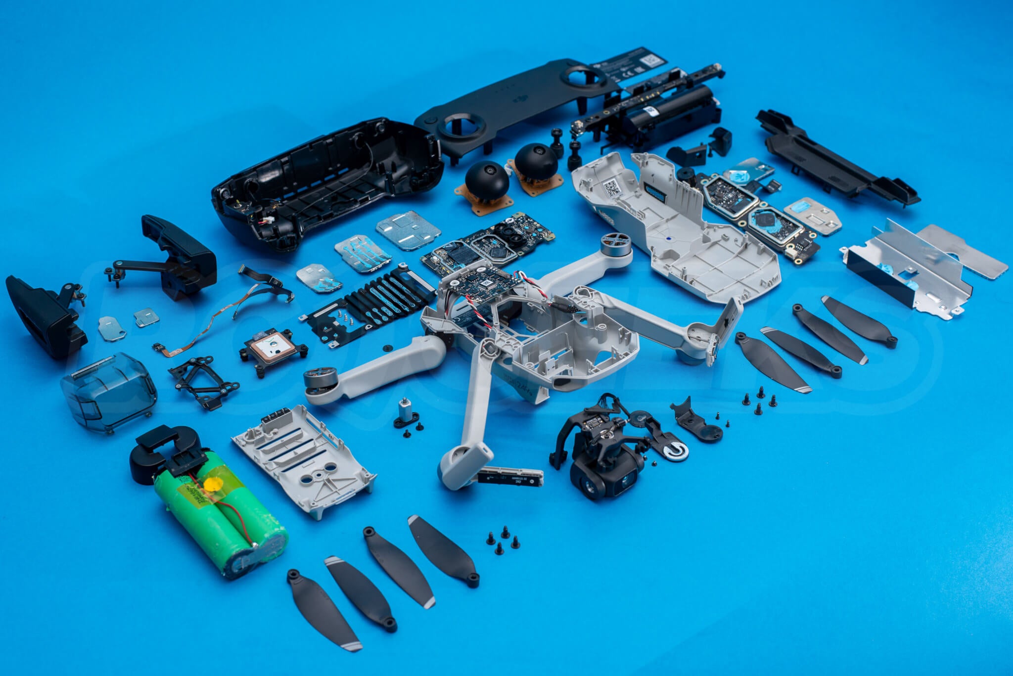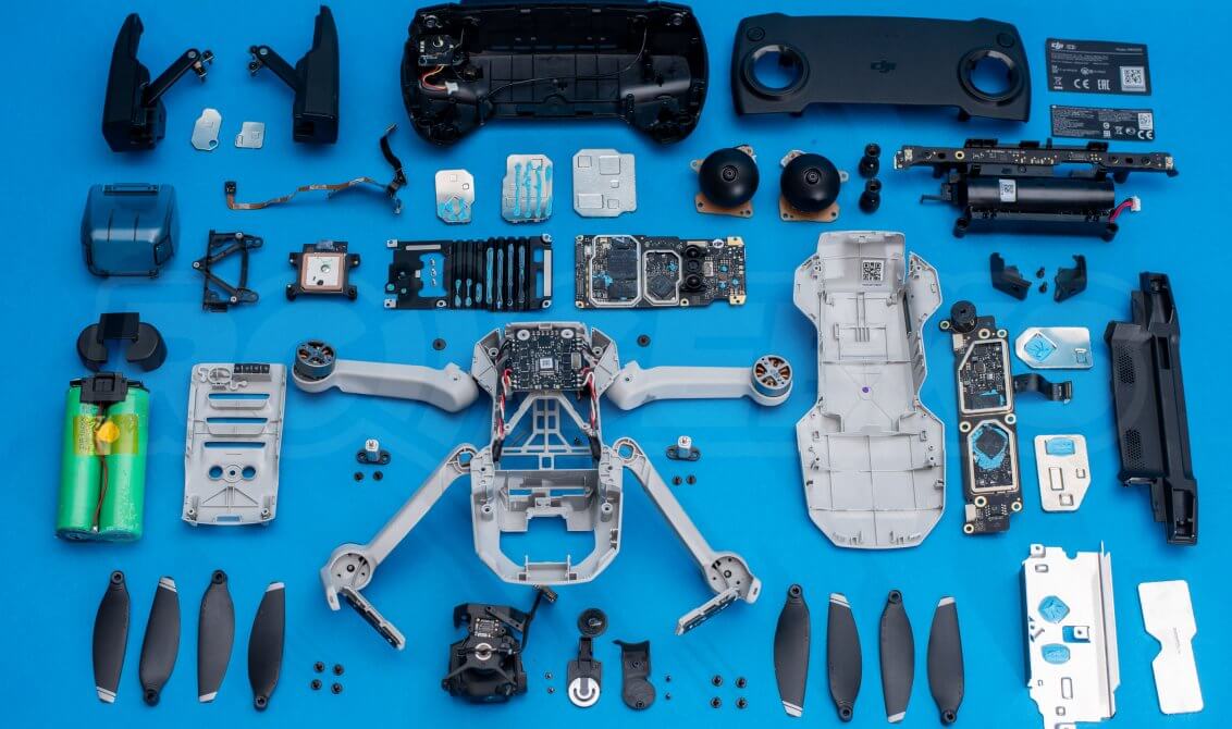
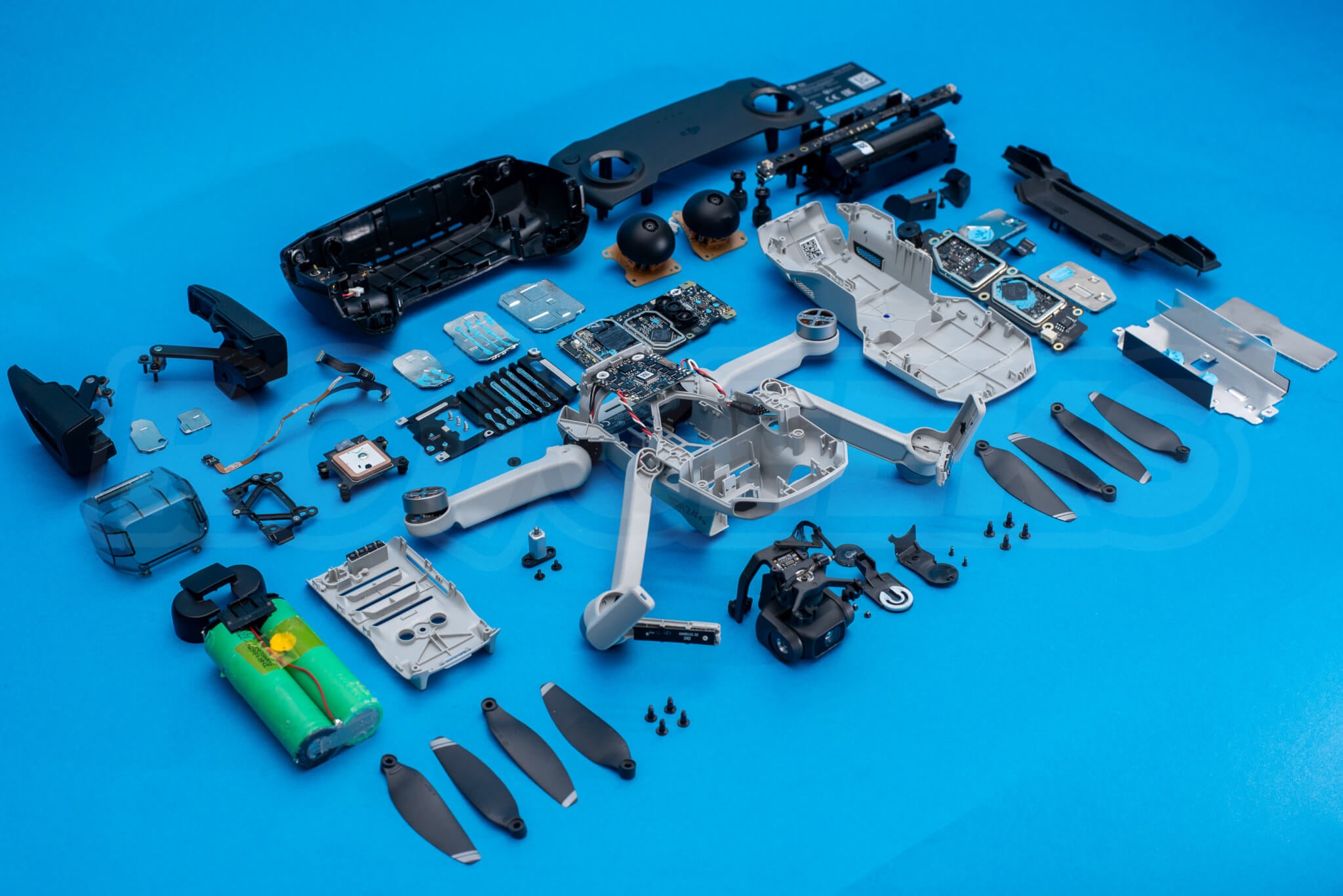
It has become tradition here at RC Geeks to tear apart any new tech we get in. We love to see how the manufacturer has put it together and our engineers get first hand experience on how future repairs might be carried out. We also know it can be a useful resource for anyone trying to repair their quadcopter many months or even years down the line. We were keen to see what’s inside the new body of this latest Mavic drone so we took a brand new retail unit out of the box and began tearing it down to see how this drone really unfolds!
Please note : This is not intended to be an instructive guide for dismantling your drone, but more a documentation of our investigation into the architecture of the new quadcopter. We take no responsibility for any potentially warranty-invalidating work carried out on your Mavic by yourself, it is at your own risk.
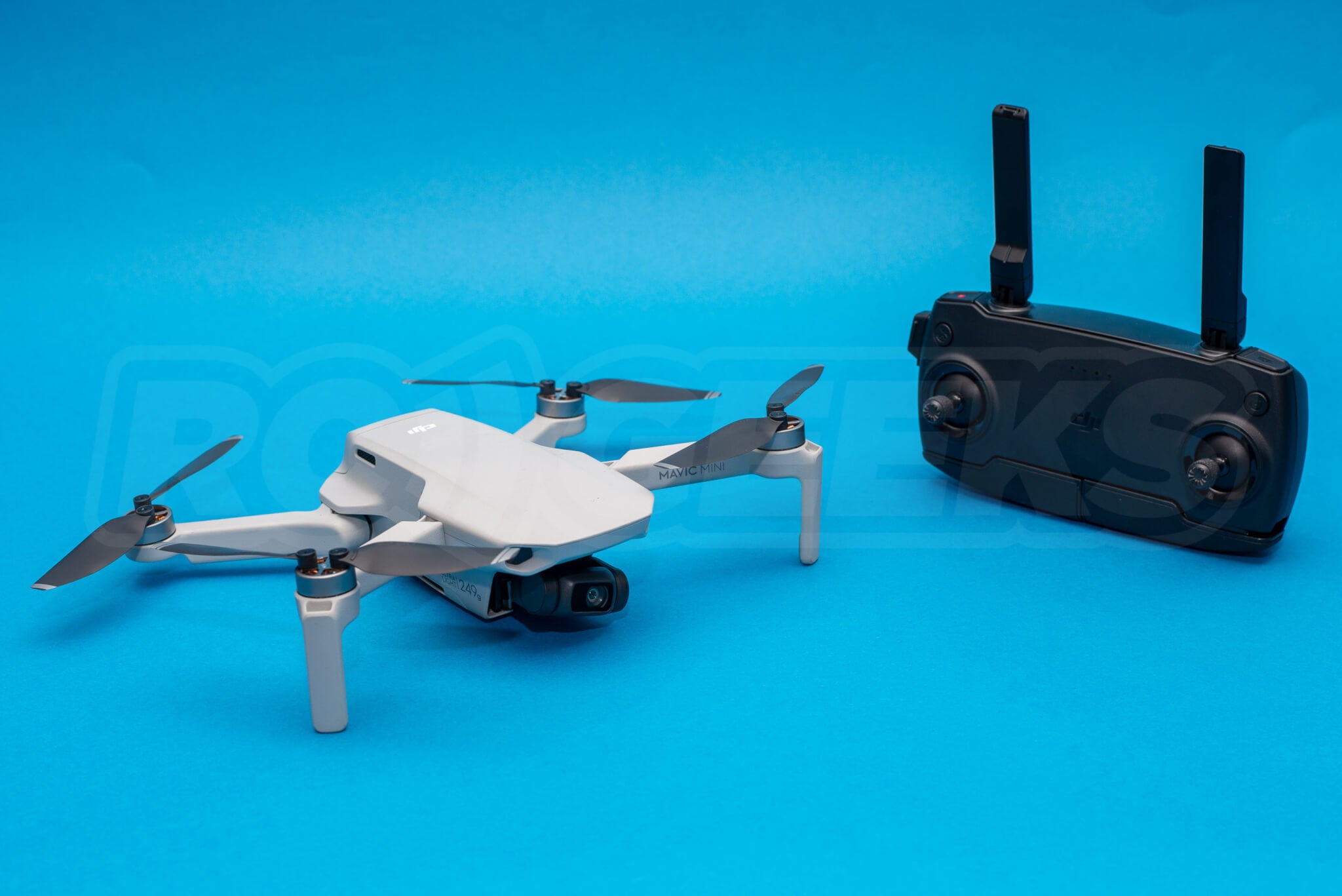
Tools required
- J00 and J000 Cross head
- Small flat head
- 1.5mm hex driver
- Spudger or plastic pry tool
- Sharp craft knife
Before you start, remove your memory card and battery!
Removing the Propellers
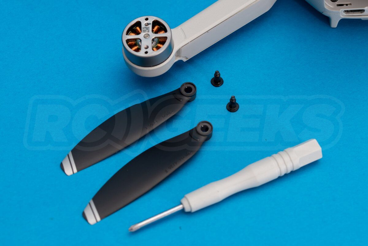
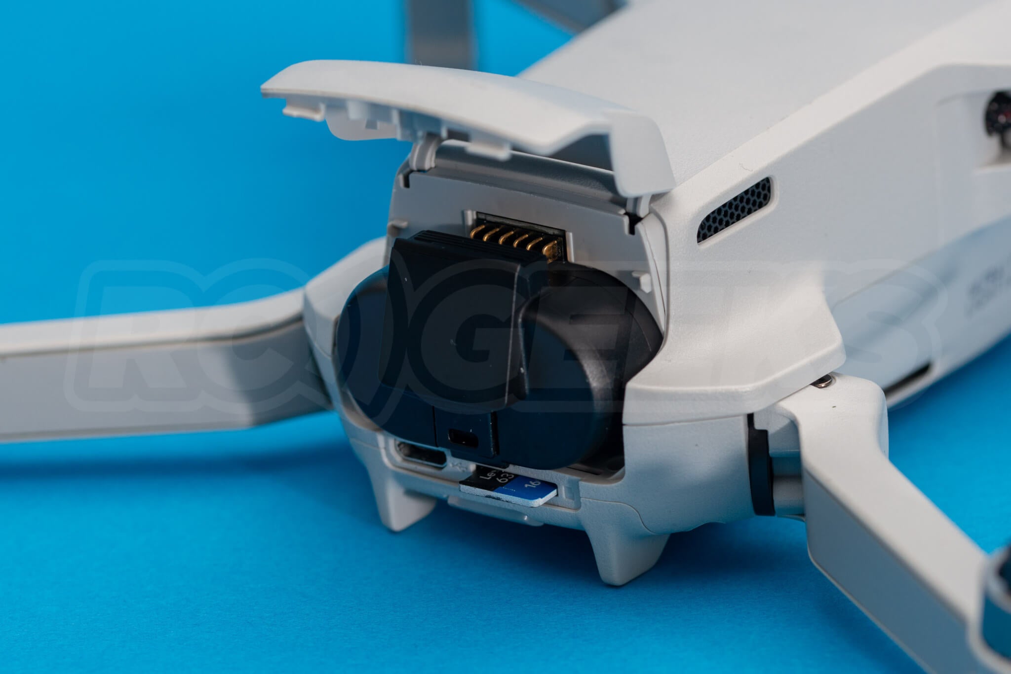
Using the supplied cross-head screwdriver, remove the two screws from each motor that retain the individual propeller blades.
Note that the CCW propellers on the rear left and front right motors have twin stripes on the end and marks that match on the inner edge of the blade and arm.
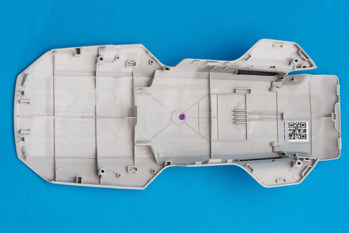
Removing the top and bottom shell
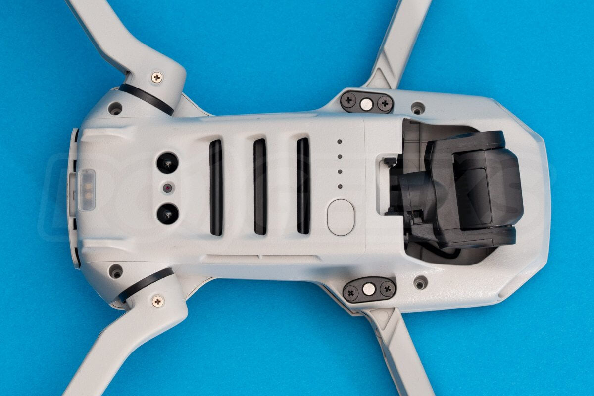
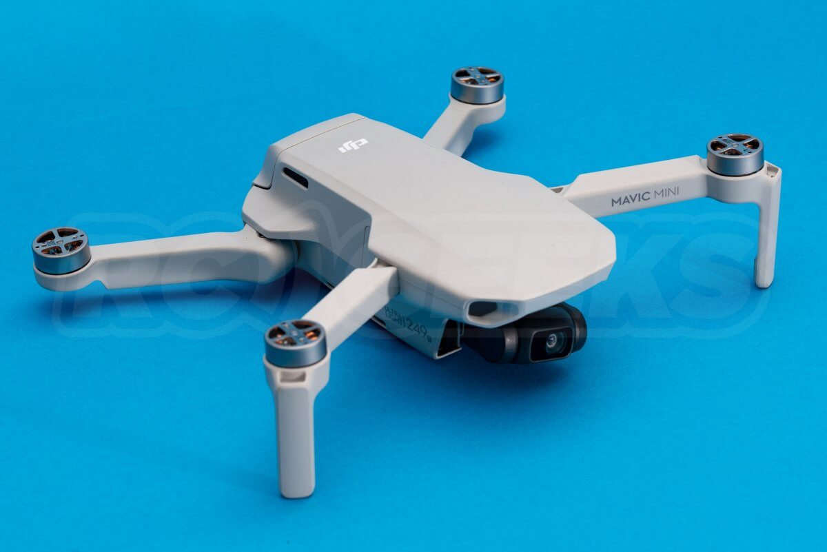
Flip the drone onto its back and remove the four cross-head screws set deep in the drone frame, these secure the top shell to the inner frame, the last shot shows them removed.
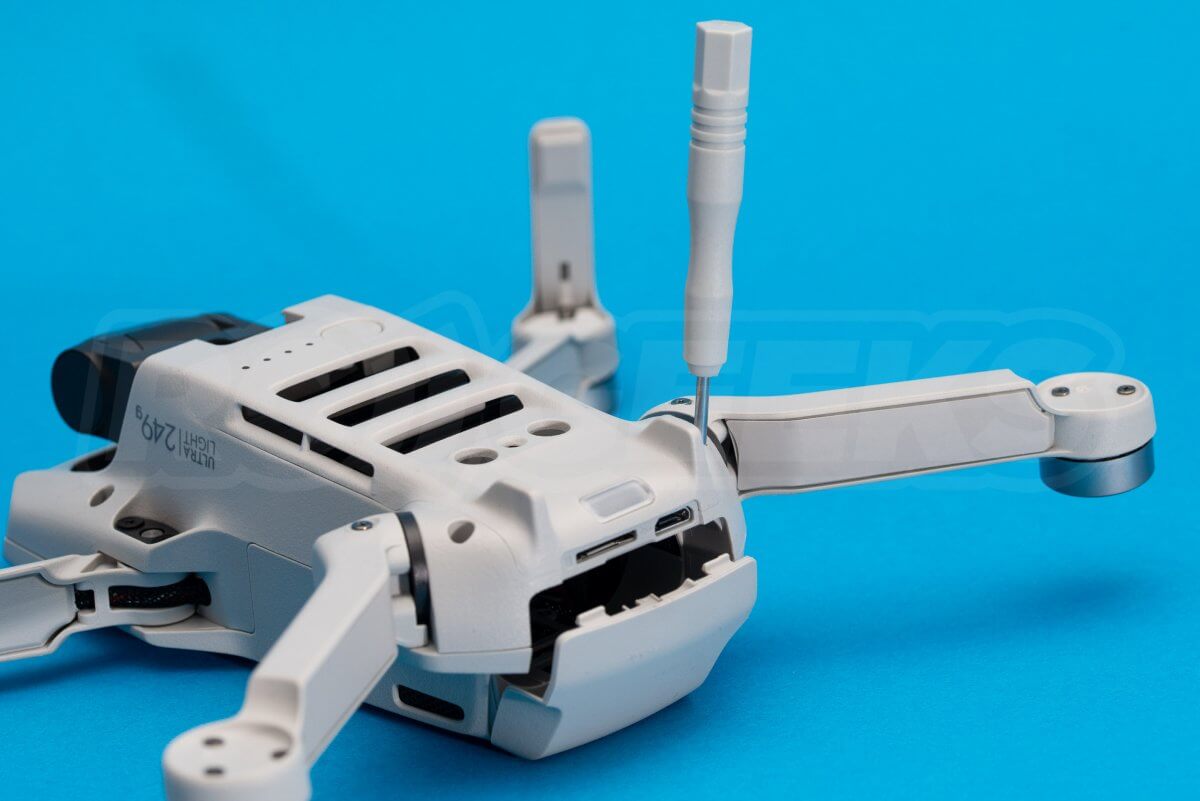
Open the battery door and remove the two screws at the leading edge of the battery tray (above the USB connection and the memory card slot) that secure the bottom panel.

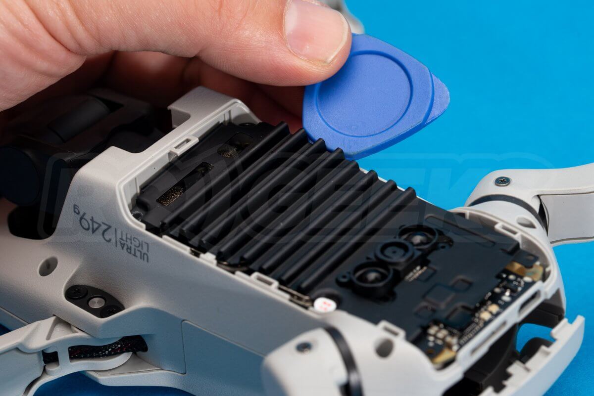
Using a plastic tool, carefully prise the thin plastic belly plate off.
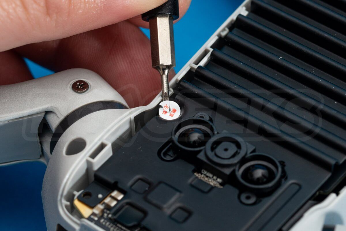
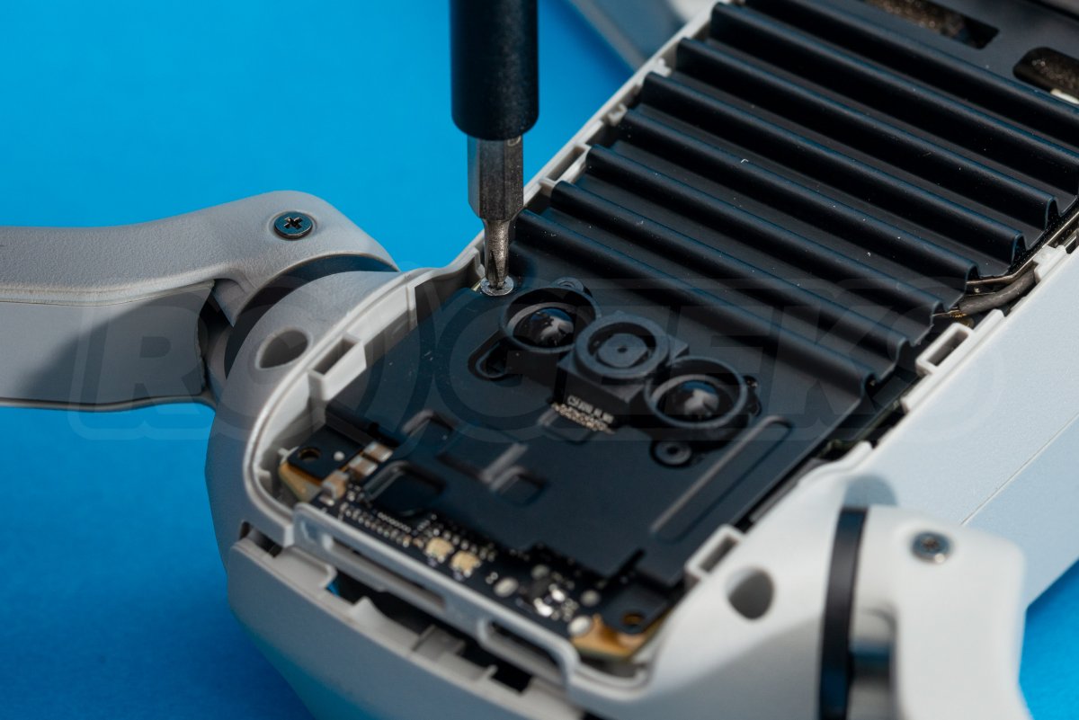
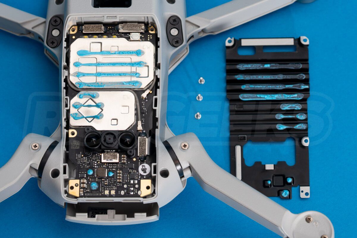
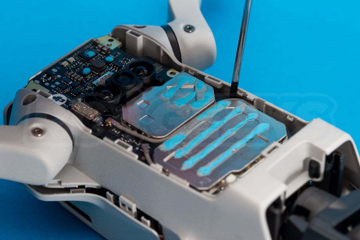
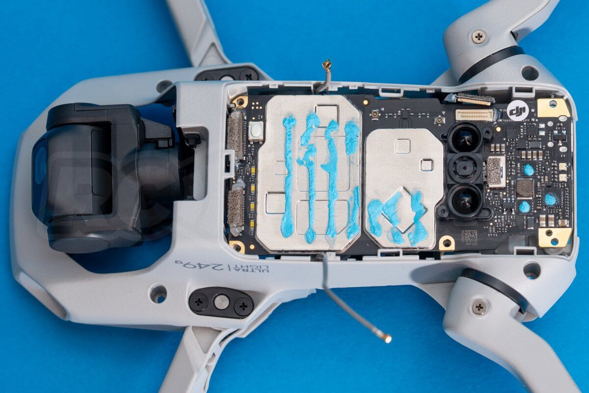
Below it is the heatsink for the mainboard. This is secured with three screws, one of which is under a security sticker next to the downward position vision sensors.
Again using a plastic tool, carefully lift the heatsink off.
Under the battery door is another warranty void sticker bridging the gap between the frame and the lid, remove this.
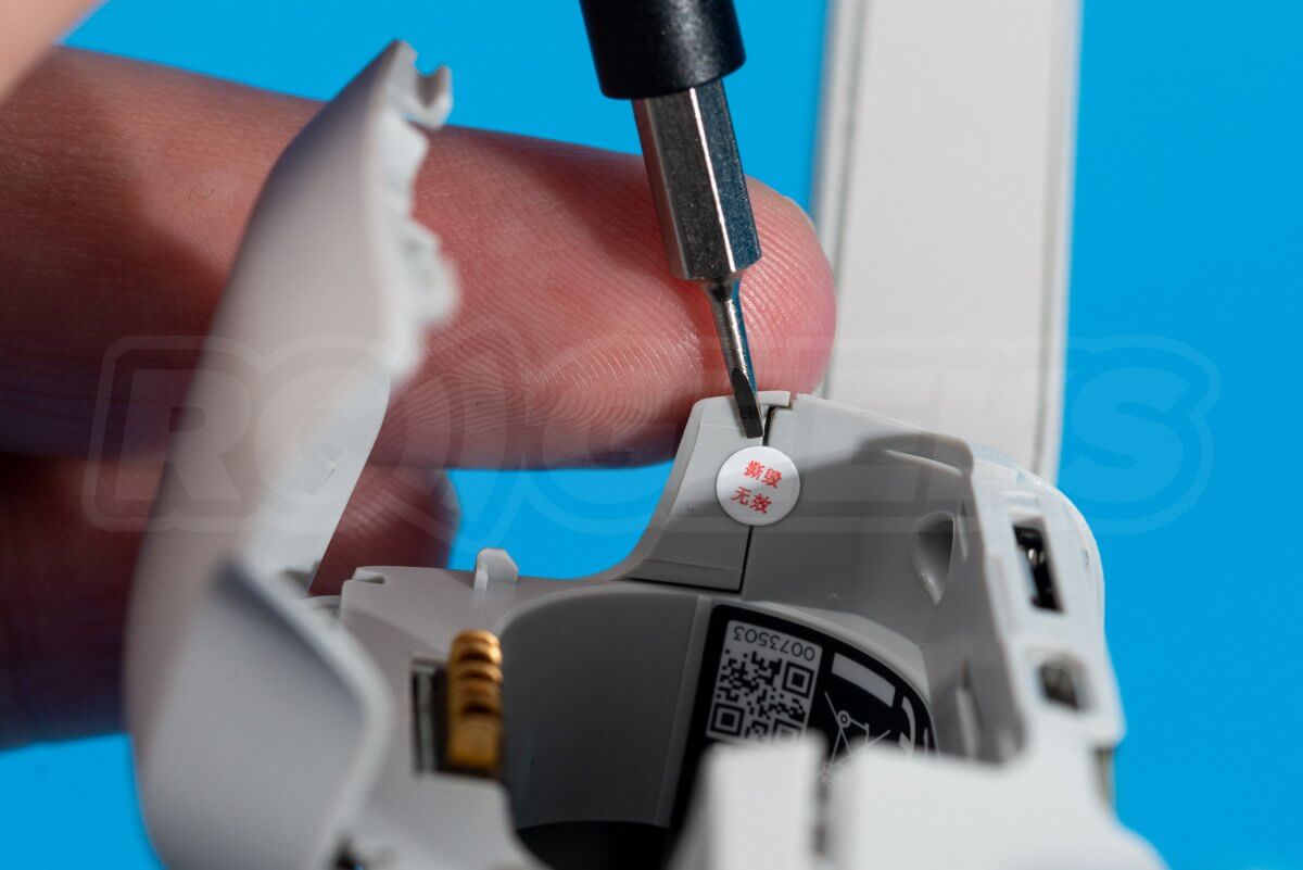
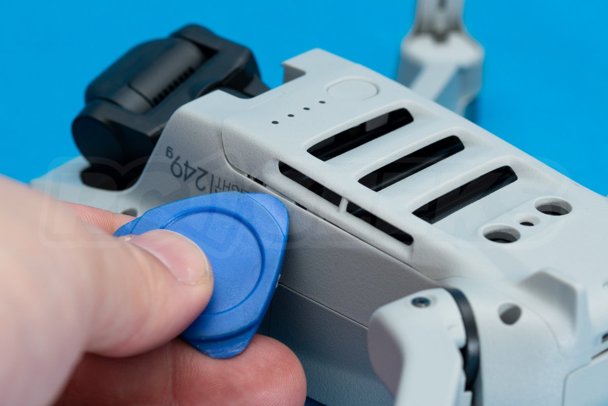
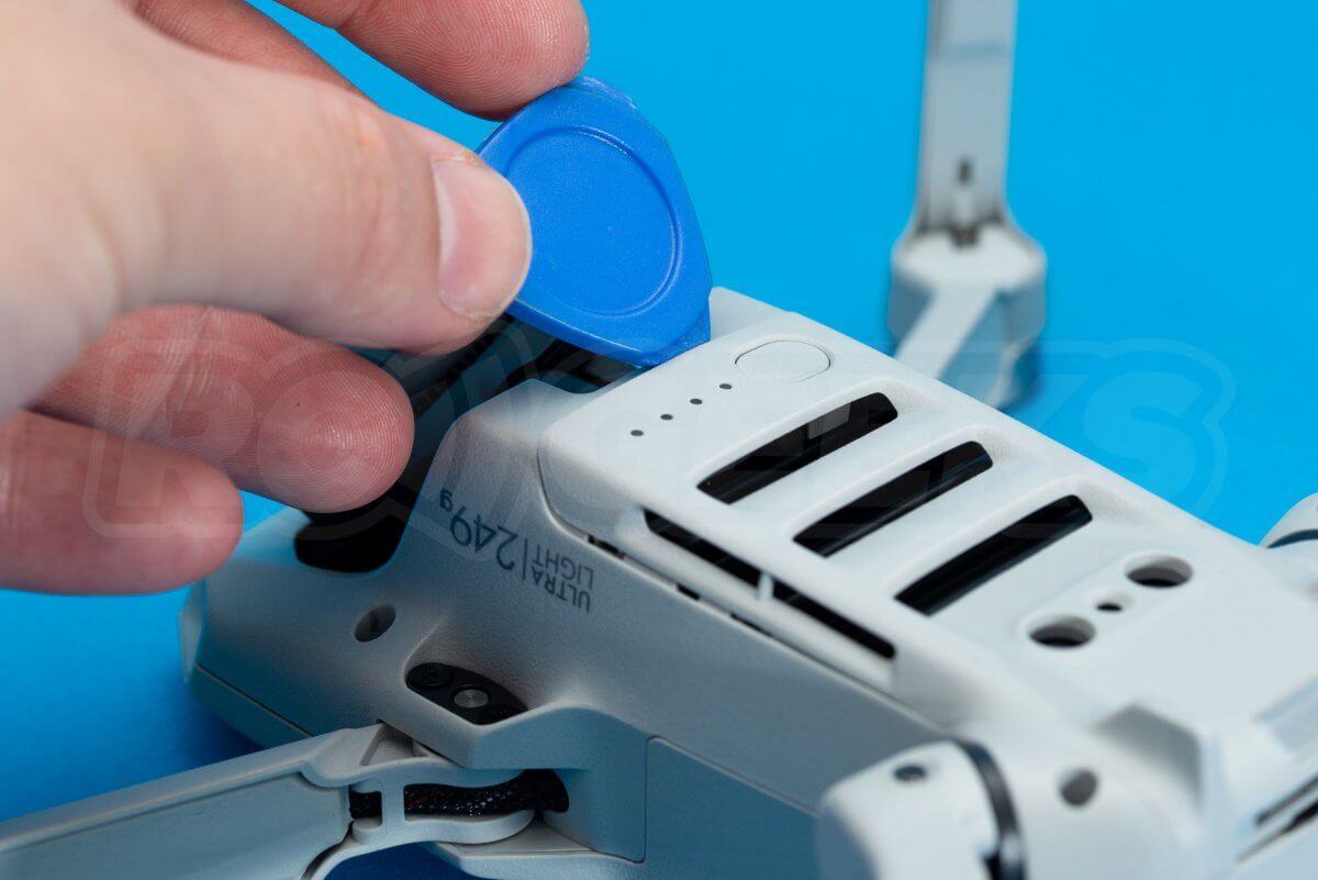
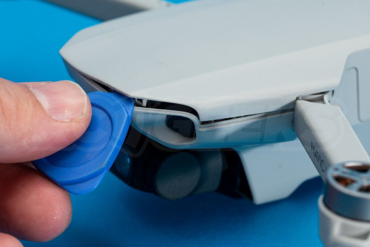
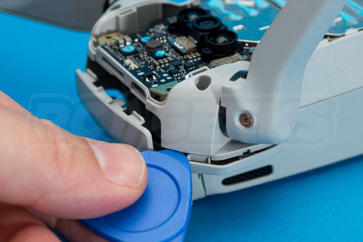
Using a plastic tool separate the lid from the frame. Start around the rear edge then jump to the front to pull the front lip up.
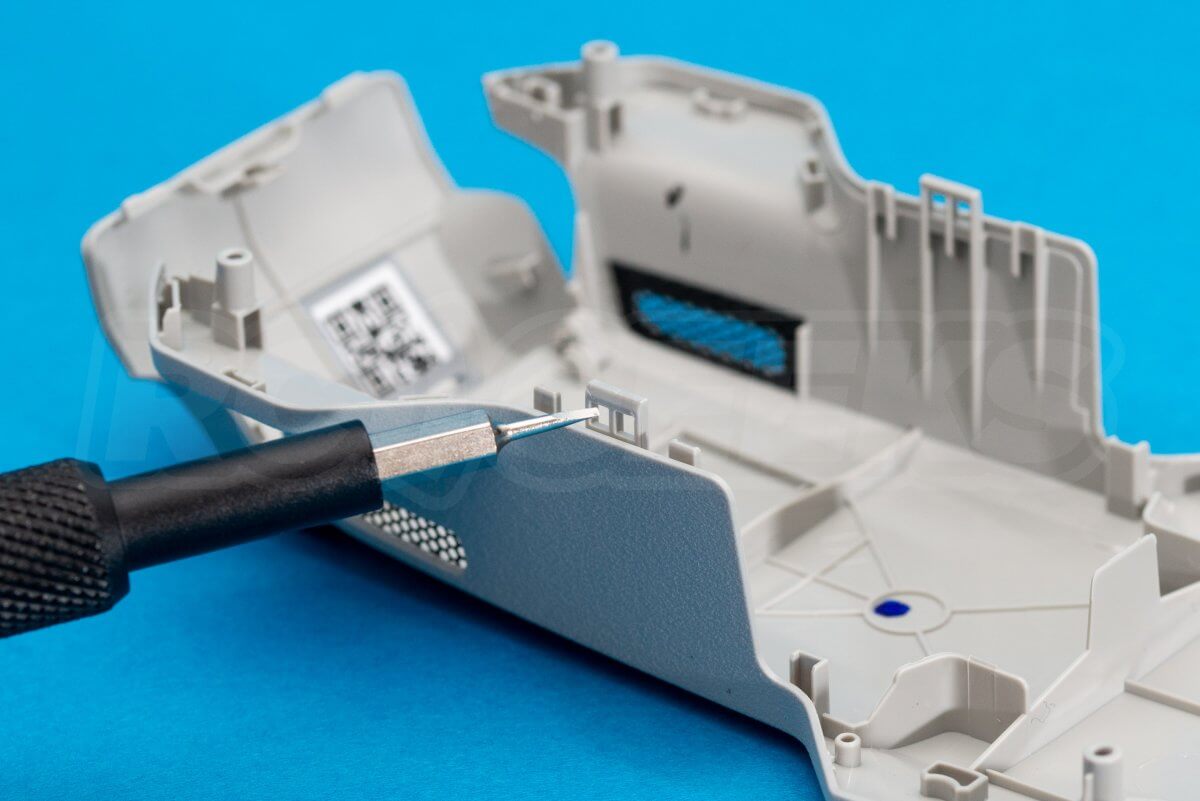
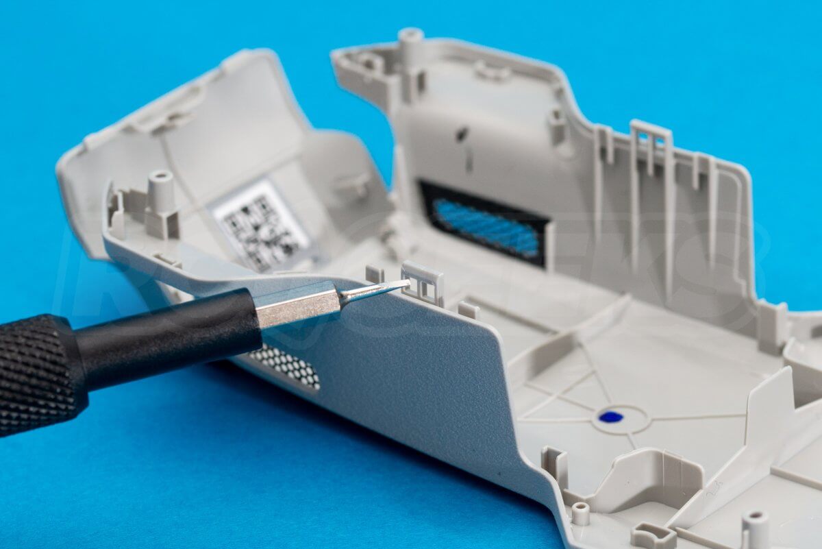
Peer into the battery cavity and you will see two clips holding the sides of the lid to the frame. These can be released with a slim screwdriver down the sides of the main-board. The second photo shows the clips in question.
The lid removed, you can see how the hinge attaches to the top. The lid itself is made of incredibly thin plastic but is flexible, rather than brittle.
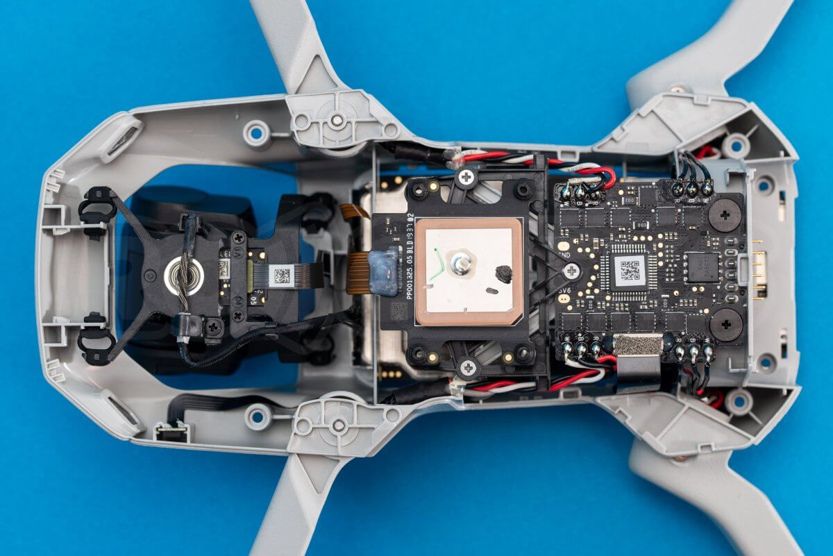
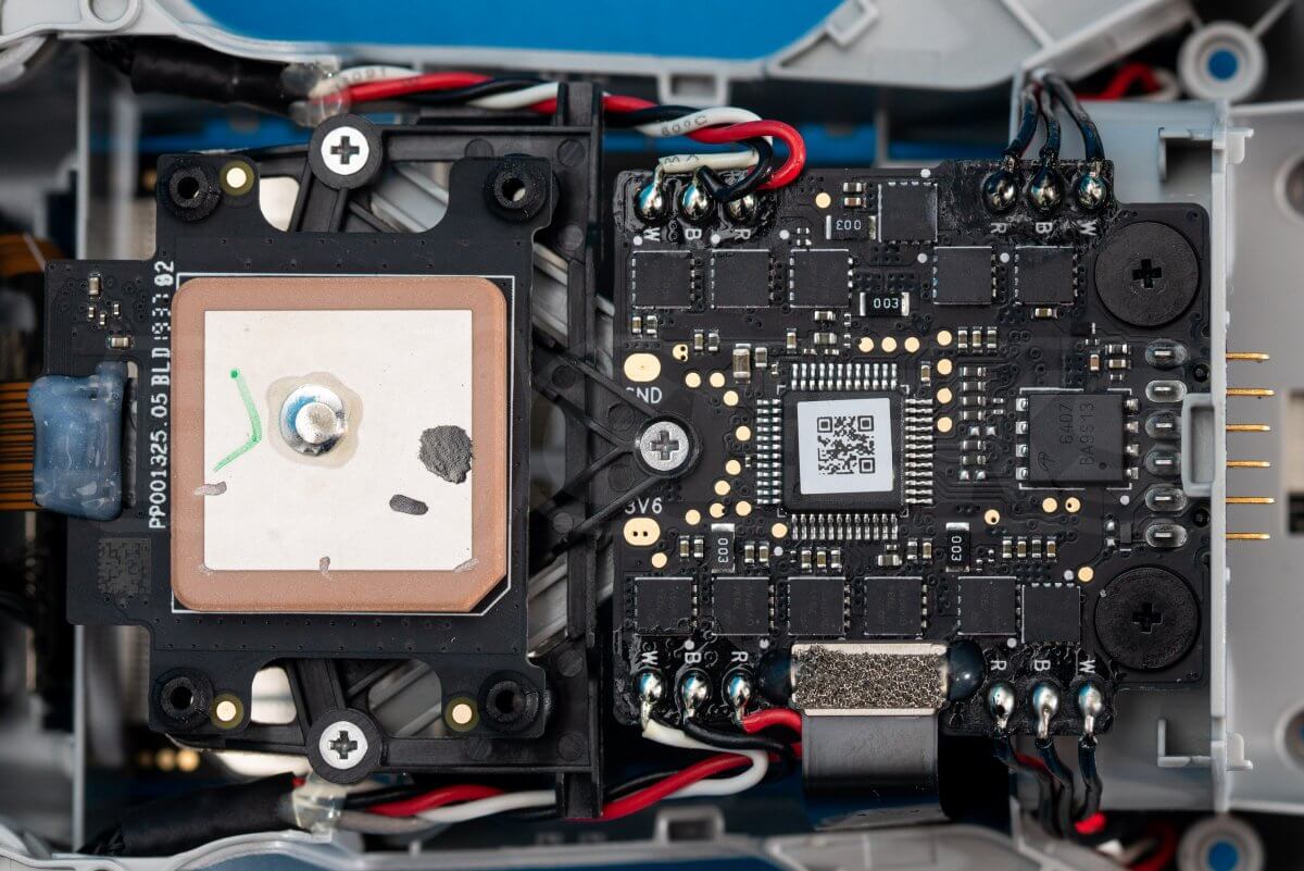
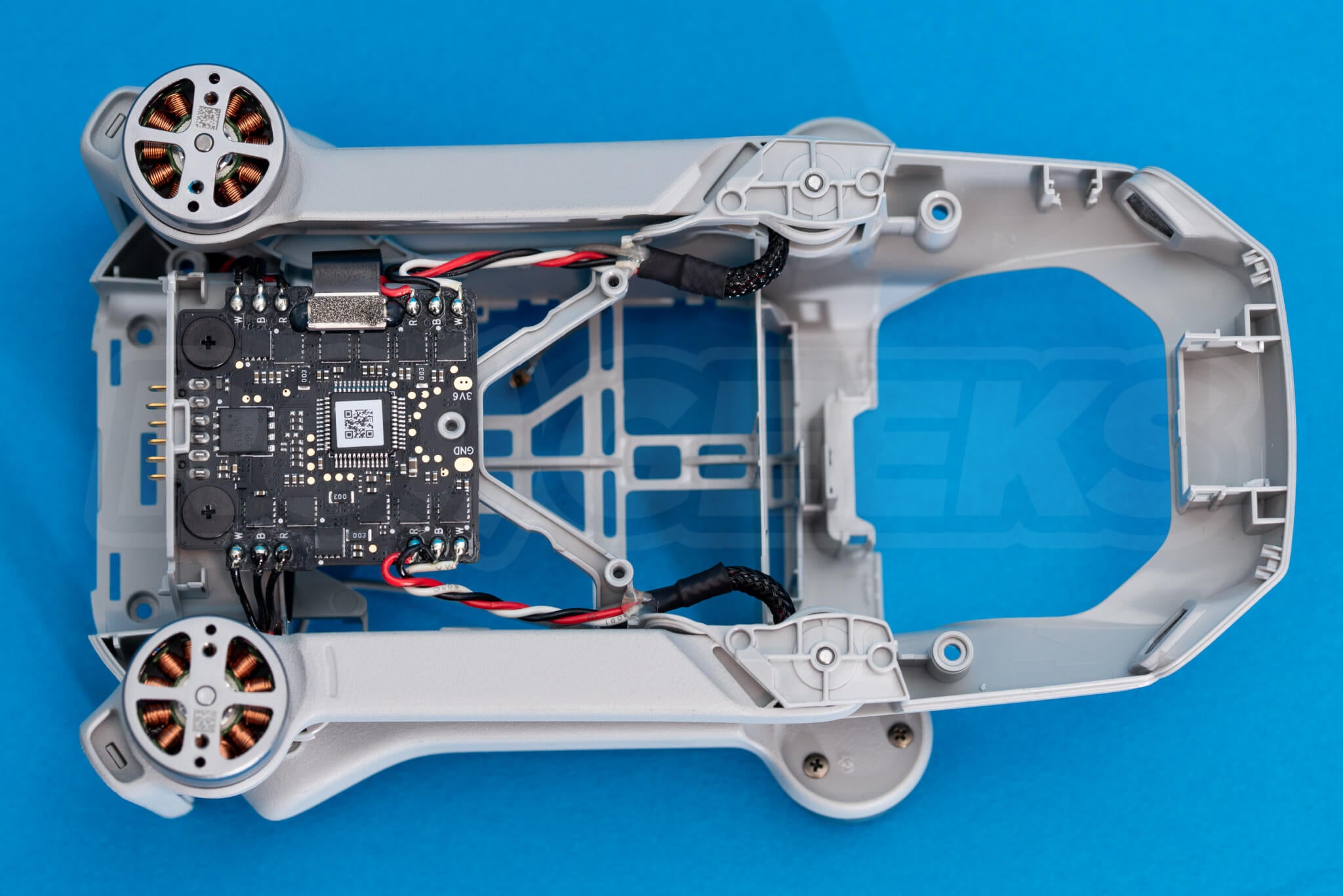
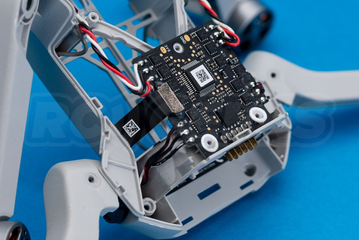
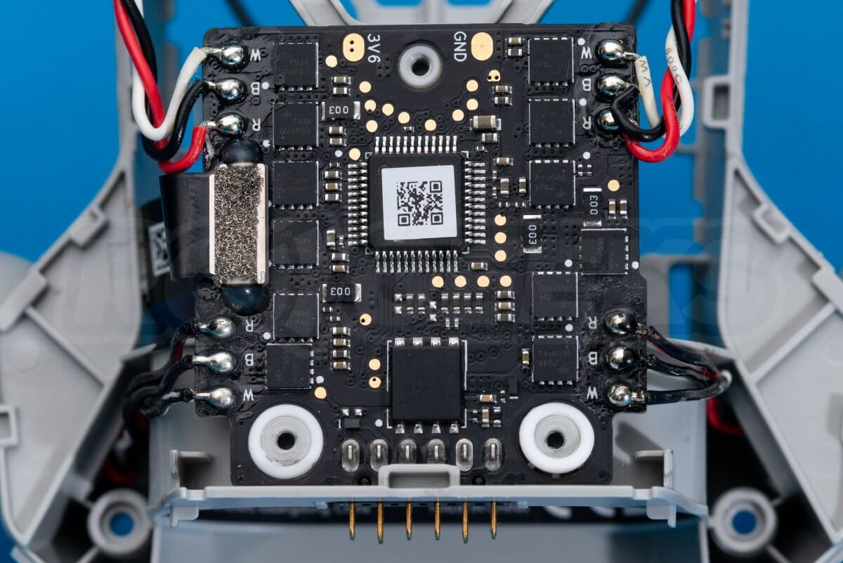
At the rear of the drone you can see the power distribution board with integral ESC, with the GPS/IMU rubber mounted on its own frame ahead of it.
Removing the mainboard
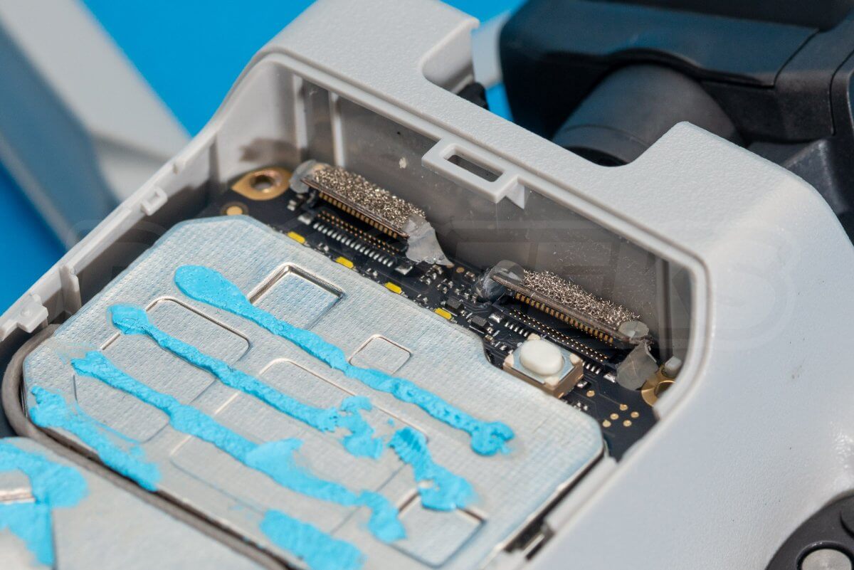
With the heatsink removed, only the cables retain the mainboard in the chassis. Using a sharp knife, carefully cut through the glue dots that retain the ribbon cable connectors to the board. Use a plastic tool to carefully lift them up and disconnect them alongside the two coaxial antenna cables. Once removed the board should look like the third photo below and is ready for removal.
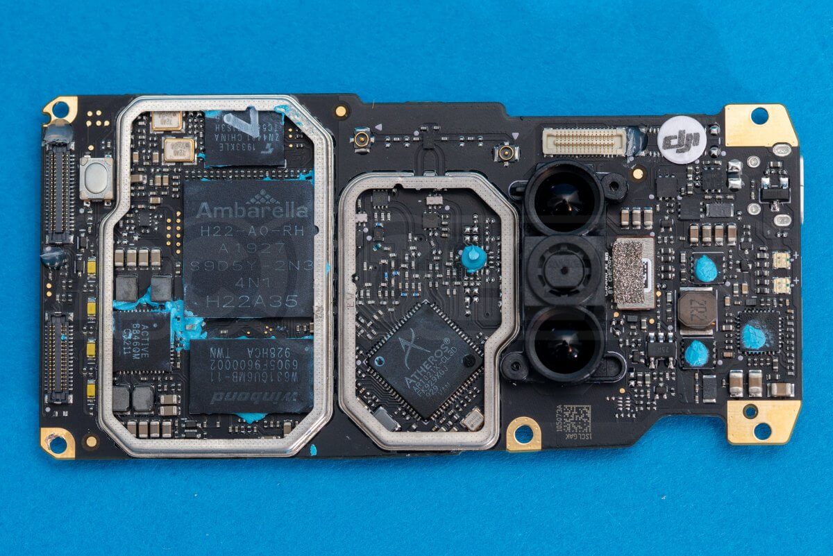
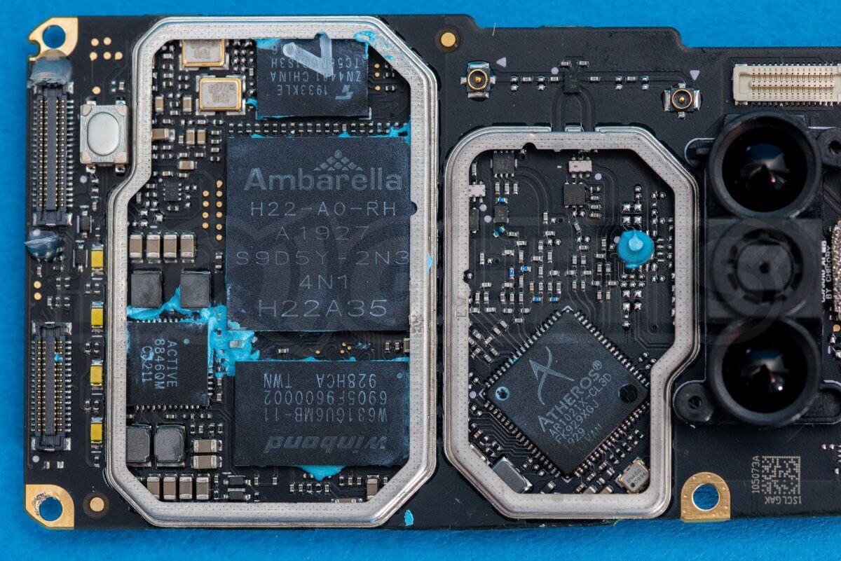
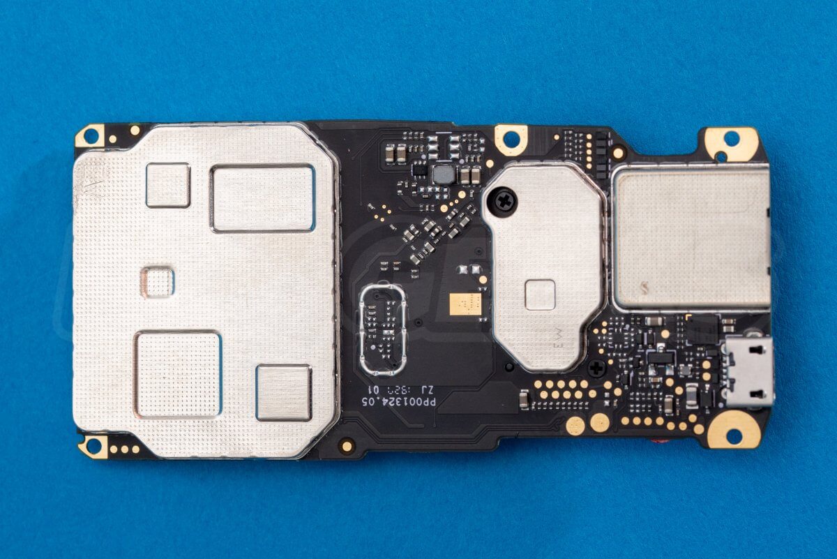
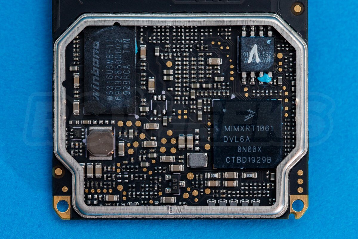
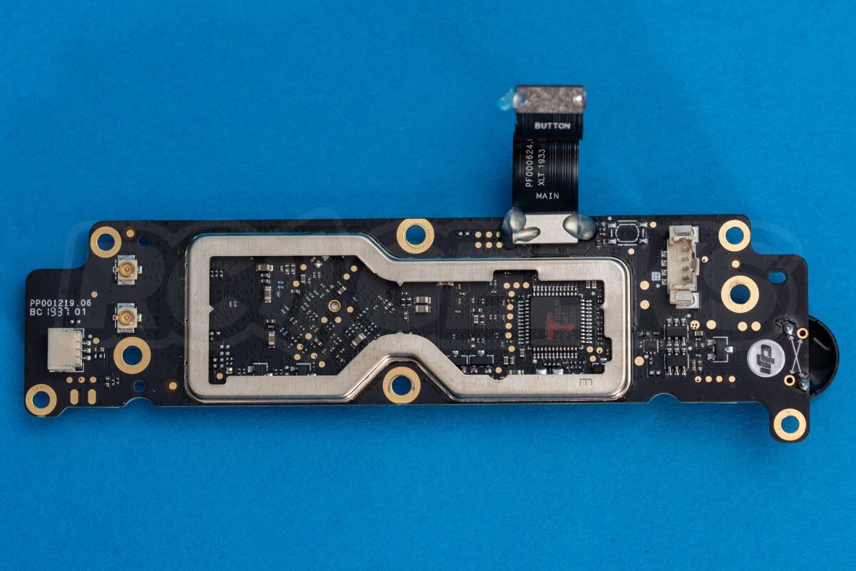
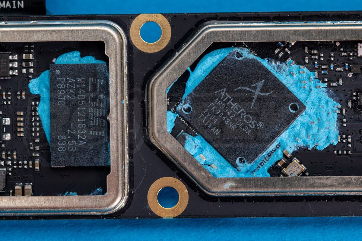
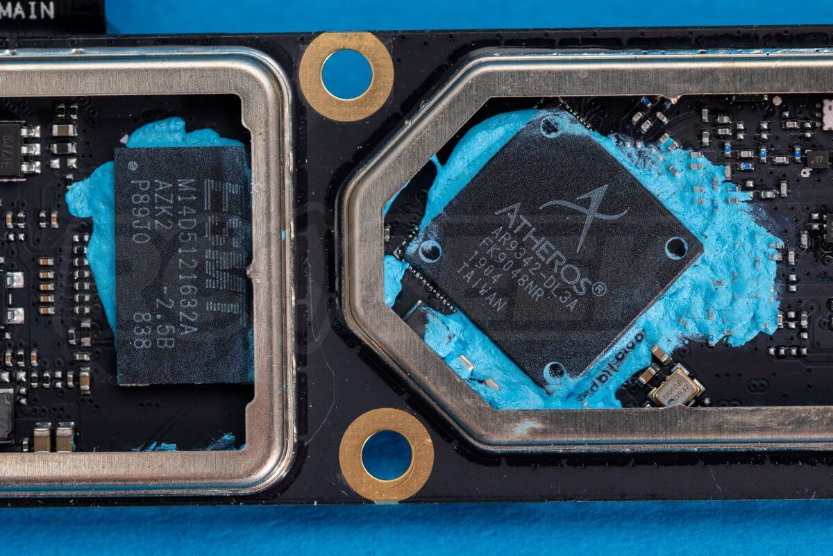
We have removed the board, heat spreaders and thermal compound for a closer look at the layout and processors employed. Firstly the ‘bottom’ of the board that faces the ground with the main processor and the transmitter chips.
Secondly we have some detailed photos of the flip-side of the same board with the SD slot.
Removing the camera and gimbal
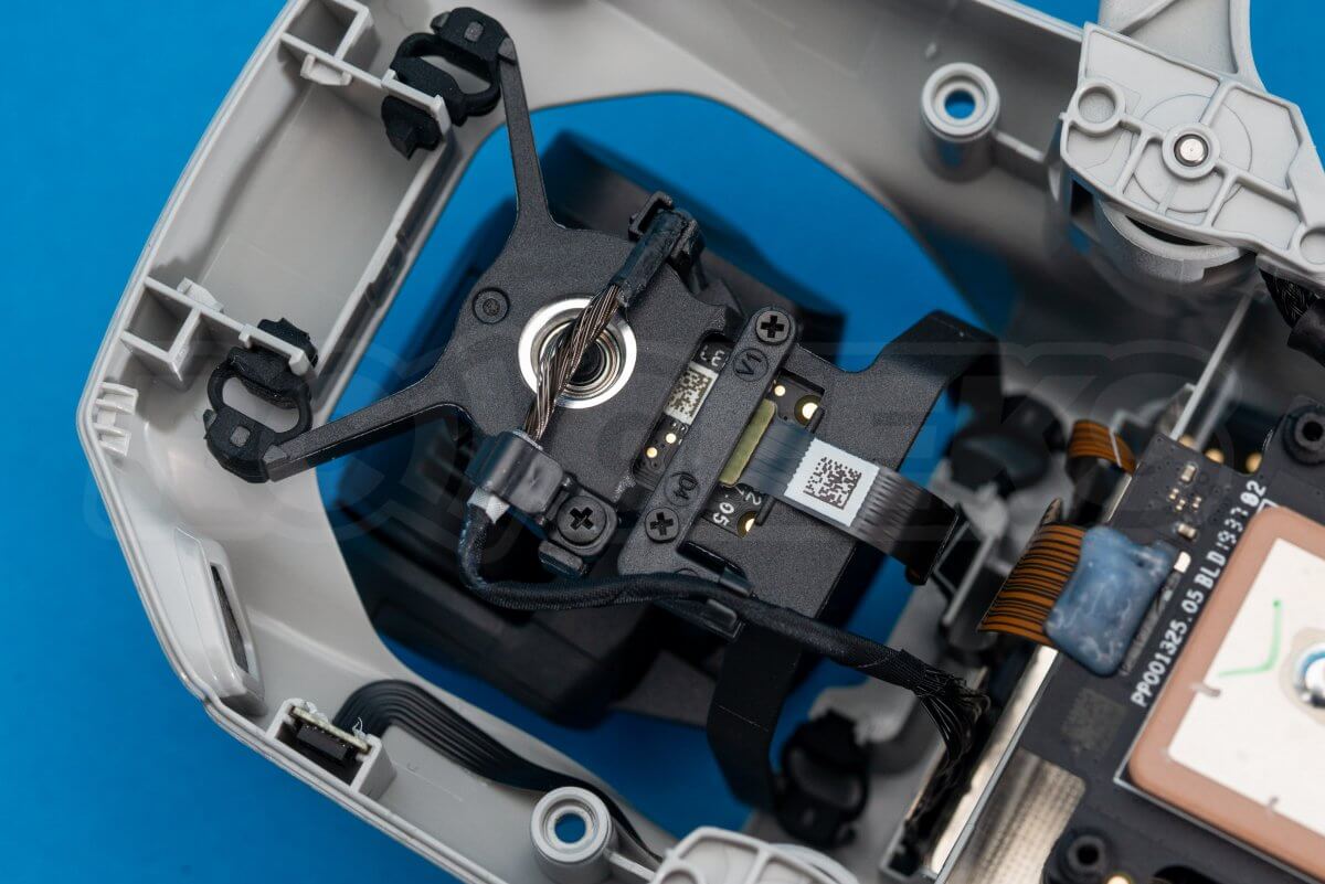
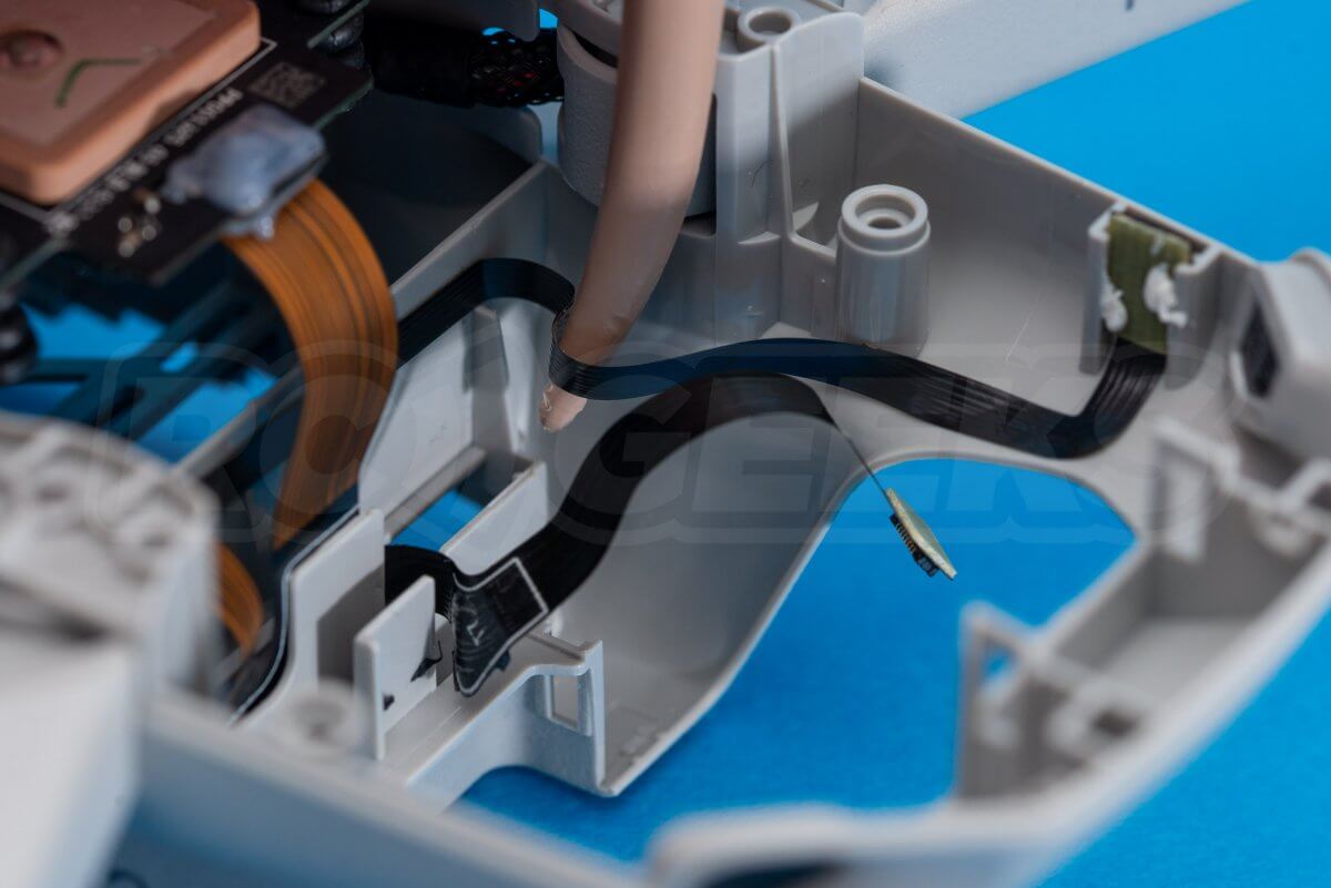
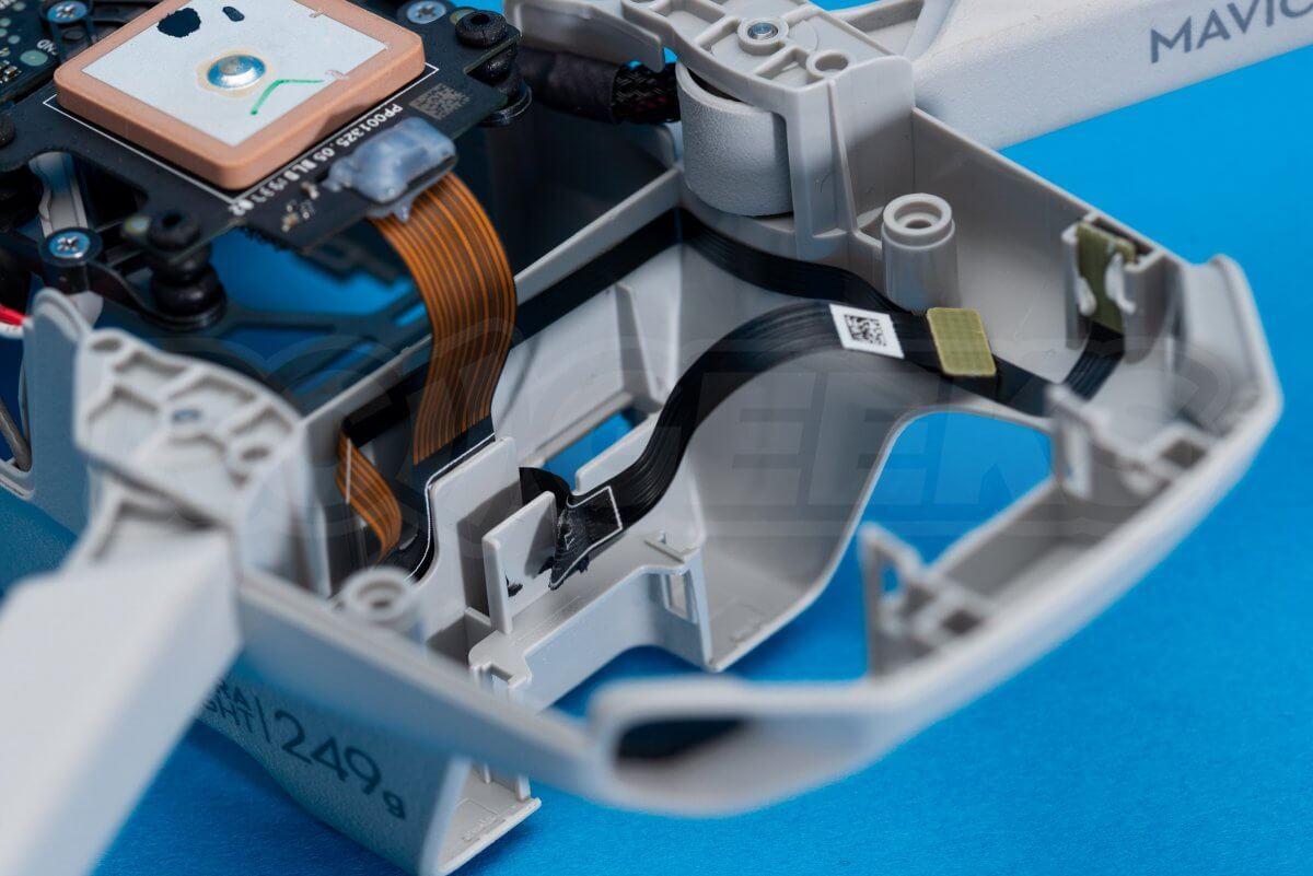
With the mainboard removed, slide the main communication cable free of the frame as seen in the second photo below.
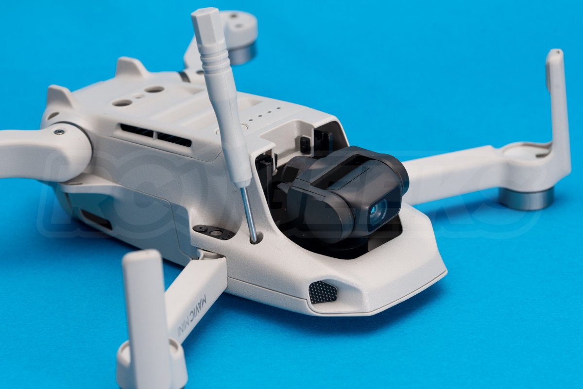
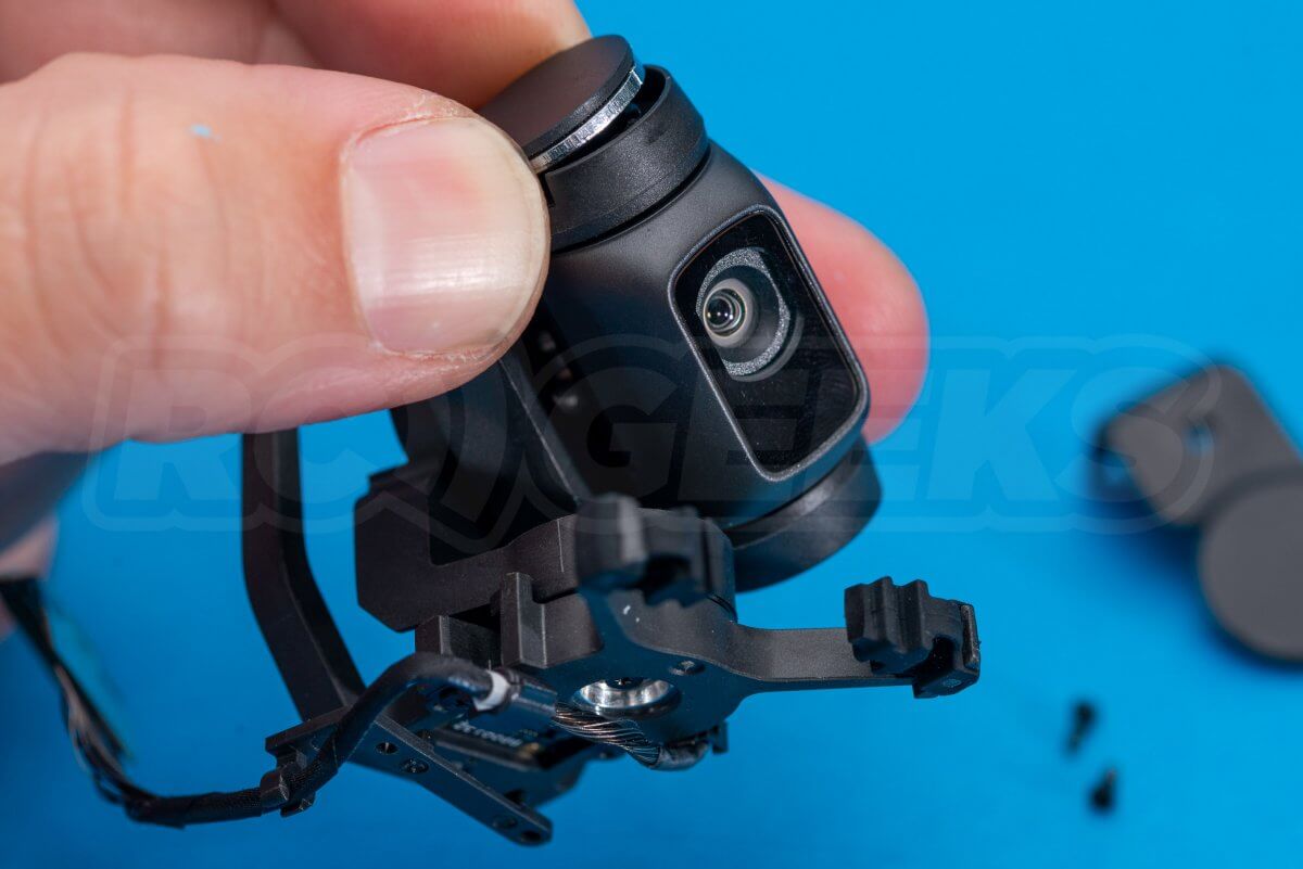
The gimbal connects to the frame via four suspended rubber mounts. These are released by gently pushing them through with a flat blade screwdriver.
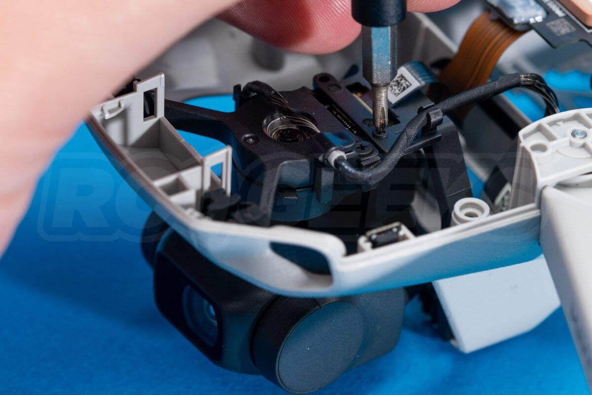
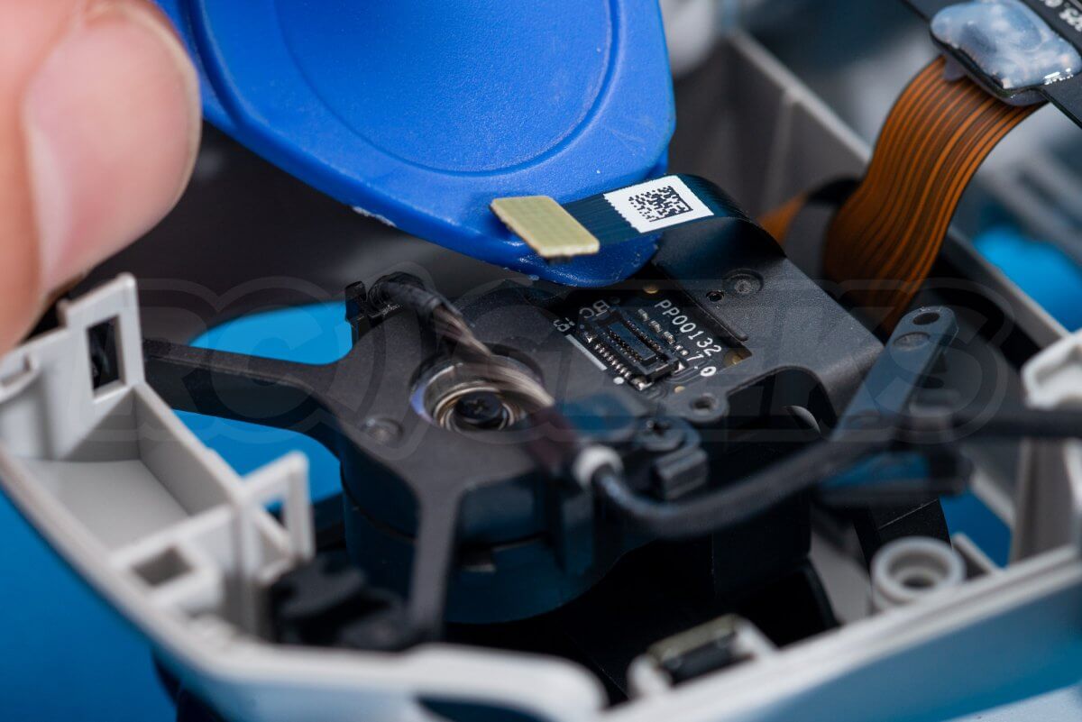
Lastly, unscrew the cable guide from the top of the gimbal and lift it out of the way to reveal the flat connection cable. Use a plastic tool to carefully release this.
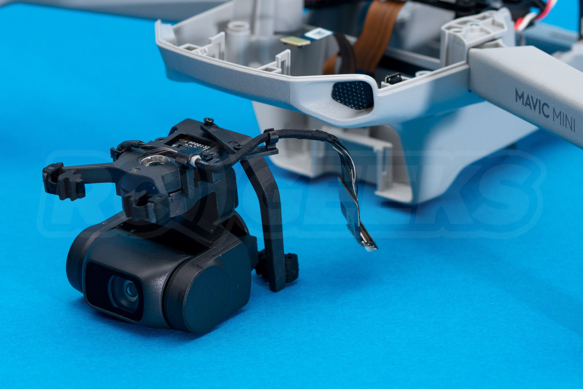
The gimbal and camera unit are now free from the drone and can be replaced if required.
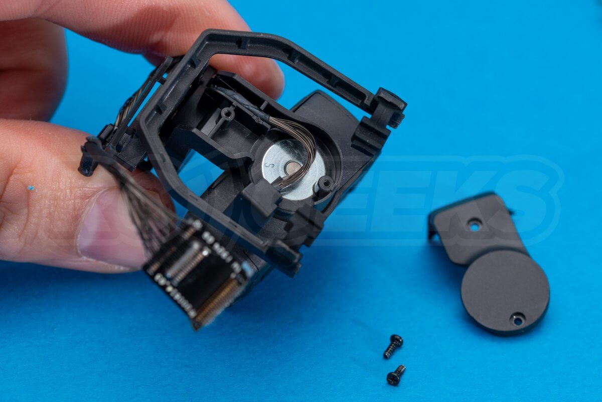
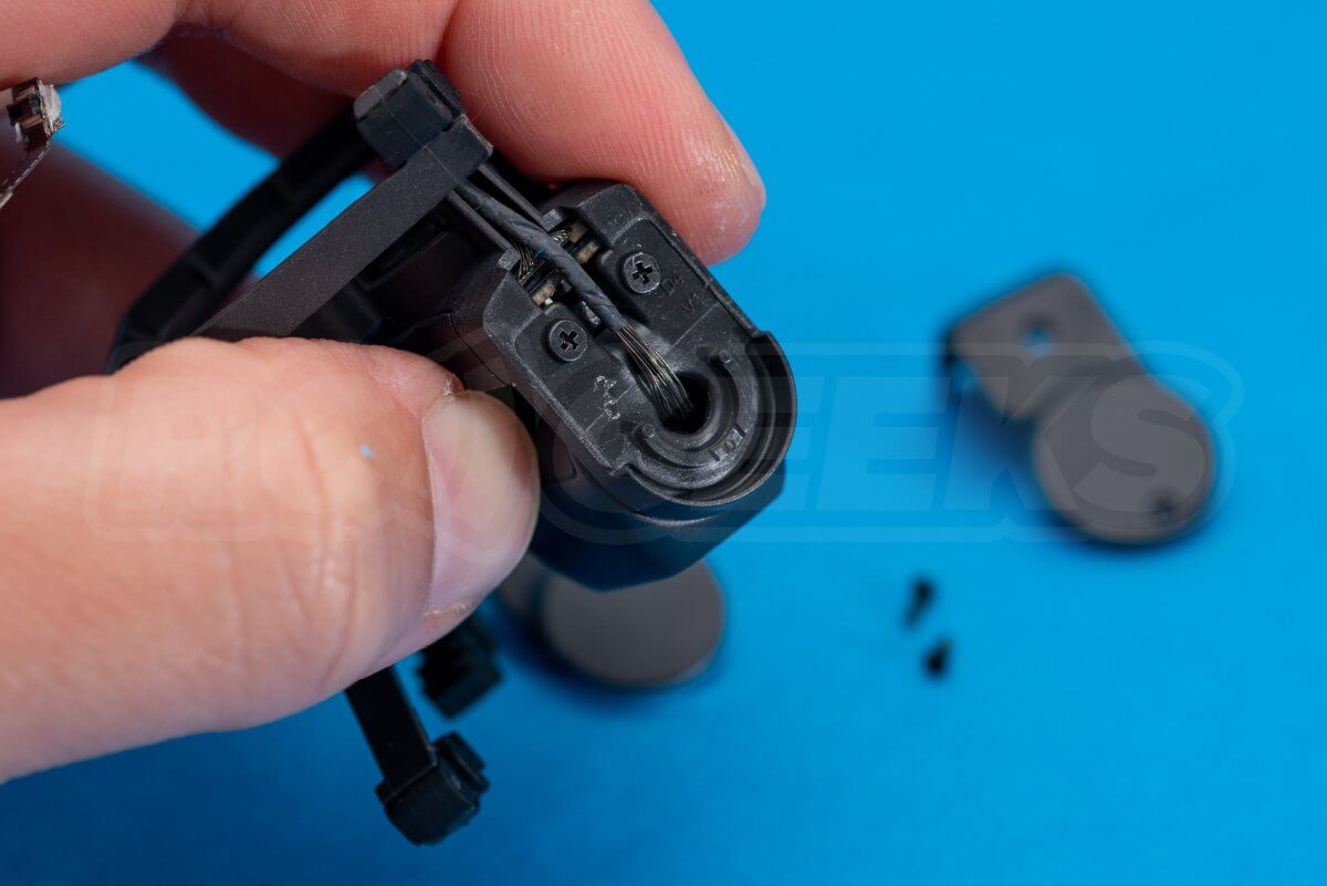
Due to the complexity of the gimbal/camera unit, DJI rarely offer spare parts for repairing them, preferring to replace them as a whole. As such we haven’t ventured much further at disassembling the unit.
Removing the communication loom
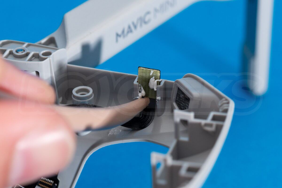
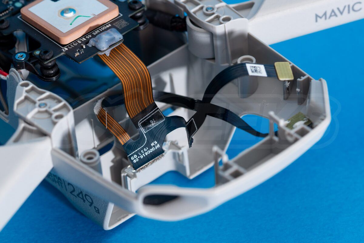
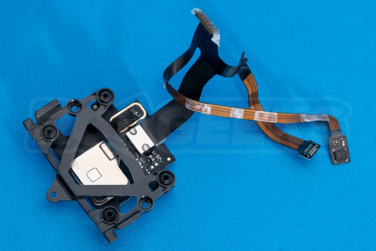
The main data loom consists of thin flex/ribbon cables that are stuck to the frame connecting the components and a device (potentially the compass) that sits on its own at the front left of the craft. Using a plastic tool the cable can be carefully lifted from the frame, noting that it connects to the GPS/IMU daughter-board.
Removing the IMU and GPS module
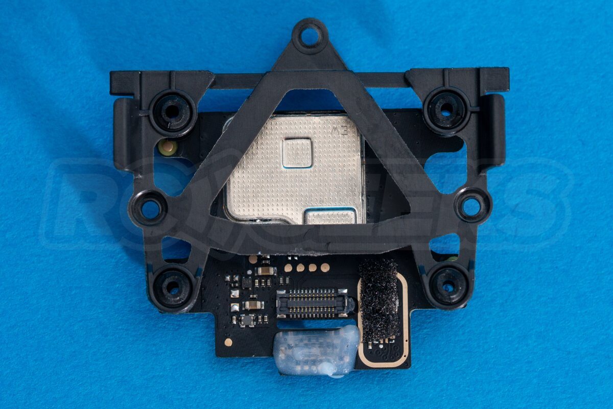
Unscrew the three cross head screws that retain the plastic mount connecting the IMU/GPS board to the frame. Once removed from the drone the loom ribbon cable can be carefully released from underneath.
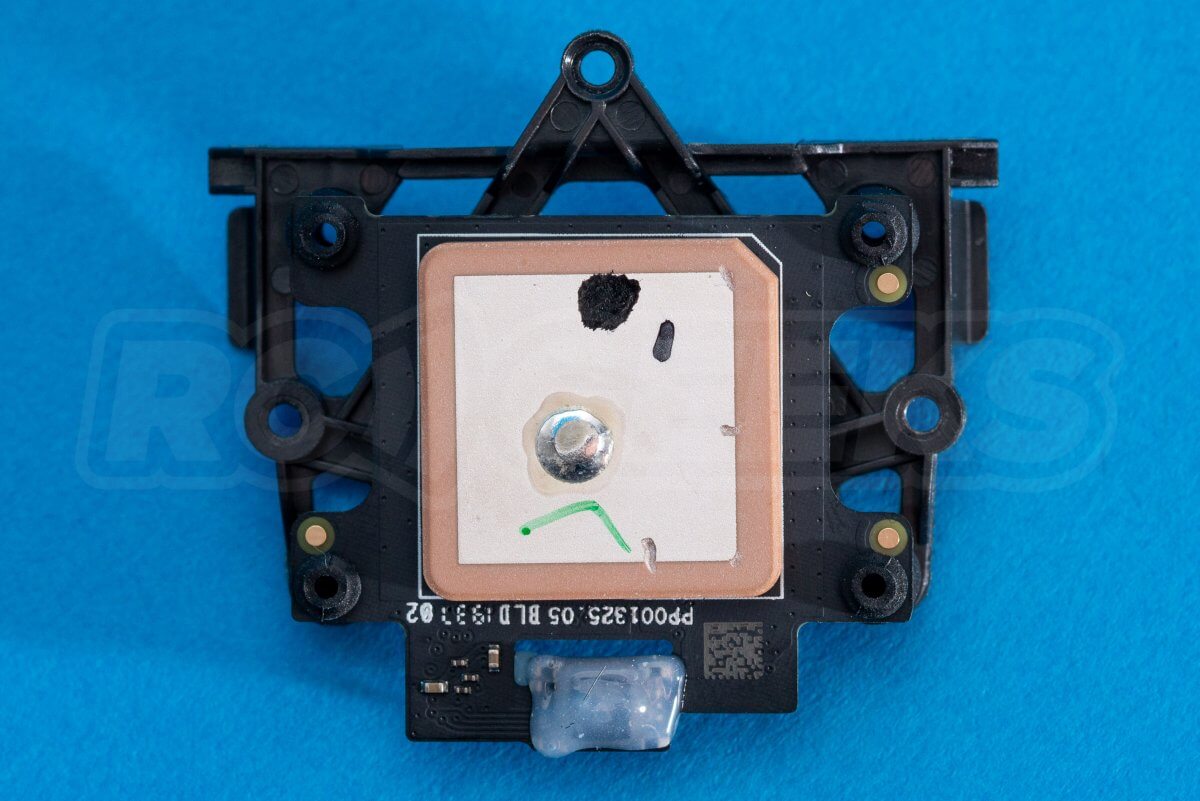
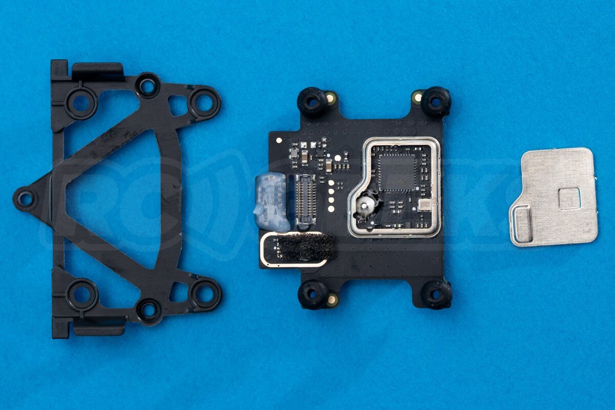
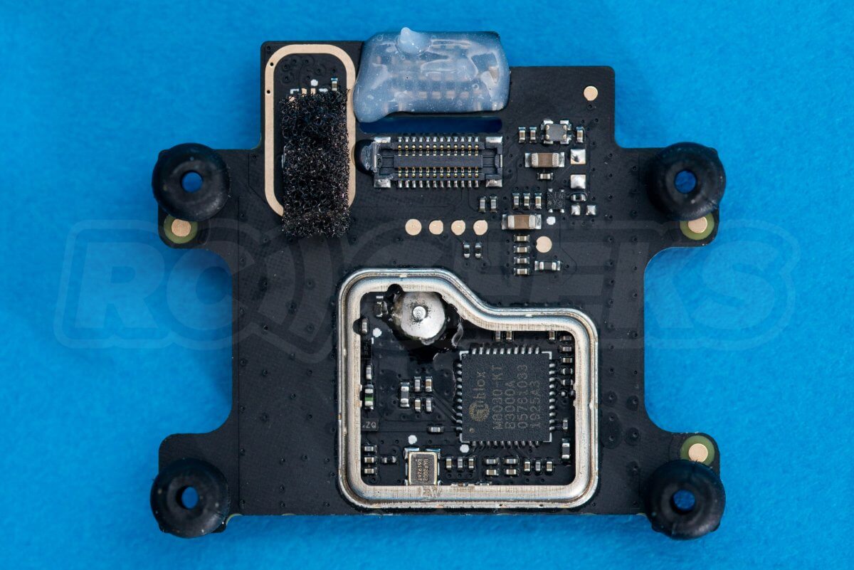
The GPS/IMU board is connected to the mount via soft rubber dampers. Removing it allows us to look at the IMU under the heat spreader and take a closer look at the GPS module.
Removing the motors
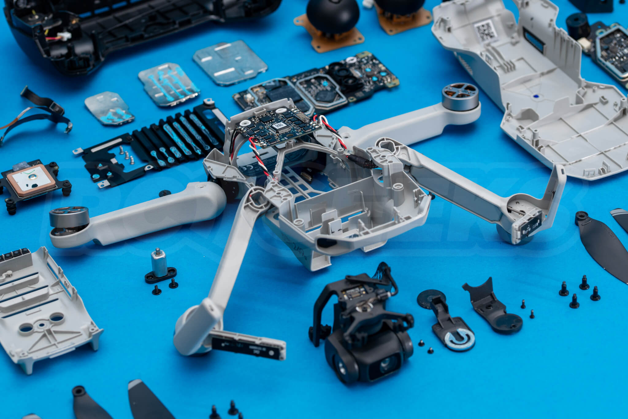
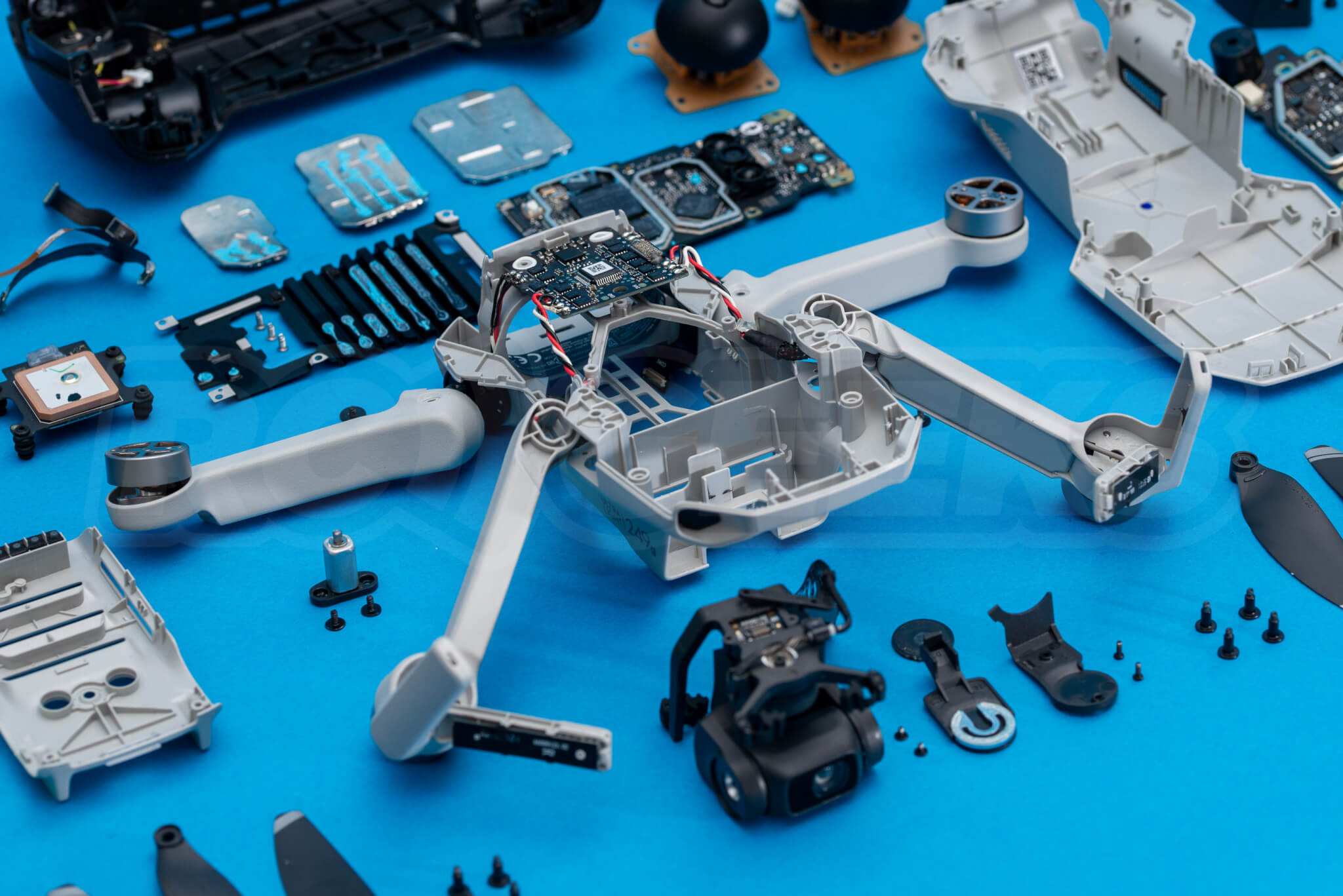
With much of the drone stripped down we are left with the following.
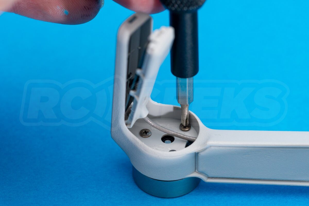
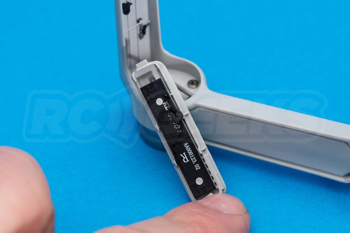
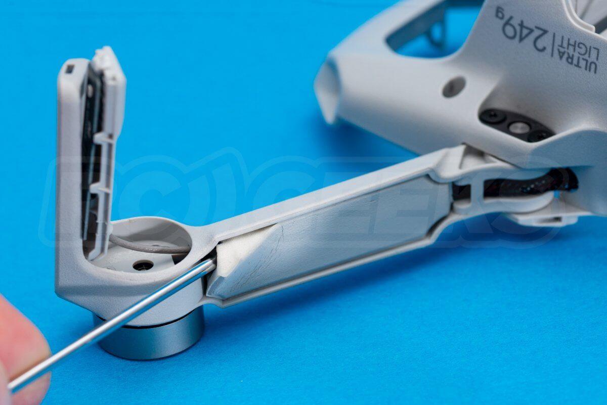
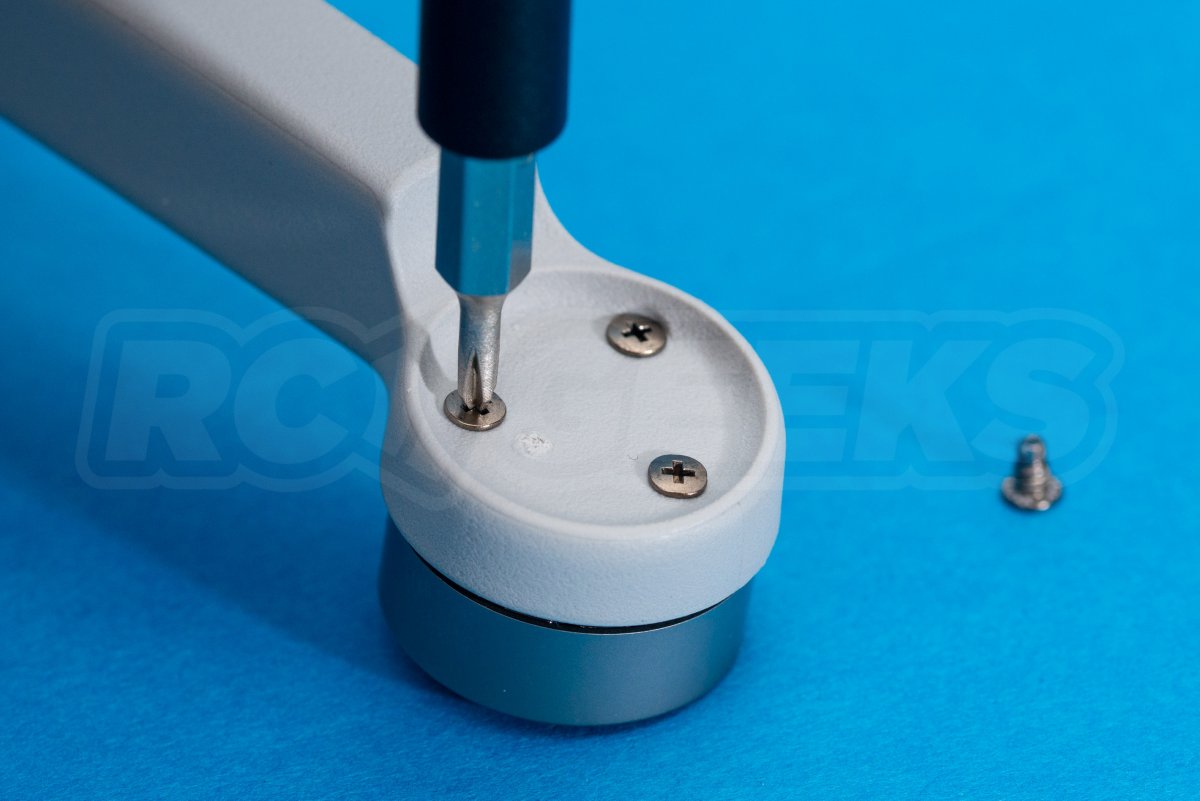
Folding the front arms out, take a flathead screwdriver and pull up the sticky-back foam pads that cover the motor screws. With that removed use the same tool to release the antenna panel from the leg.
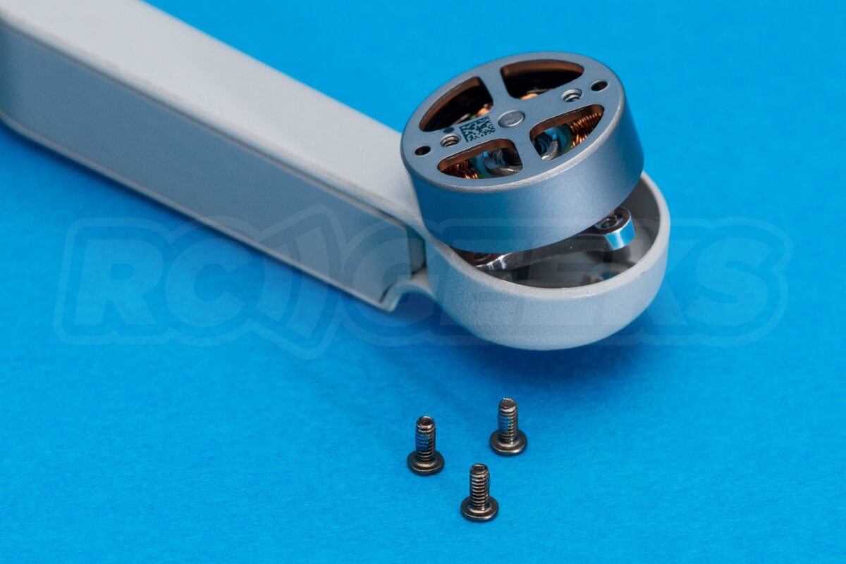
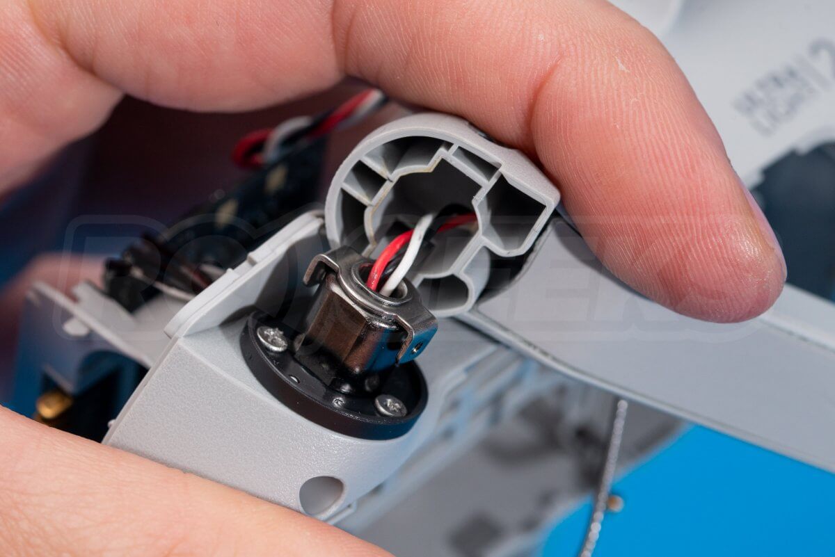
Switching to a cross head, remove the three dark screws that hold the motor to the arm. The wiring is held to the arm via a long sticky-back strip of foam, likely minimising the weight of the arms whilst keeping the clean looks. If you were replacing the motor you would need to de-solder it from the ESC board, untangle it from the antenna wire and feed it down the leg.
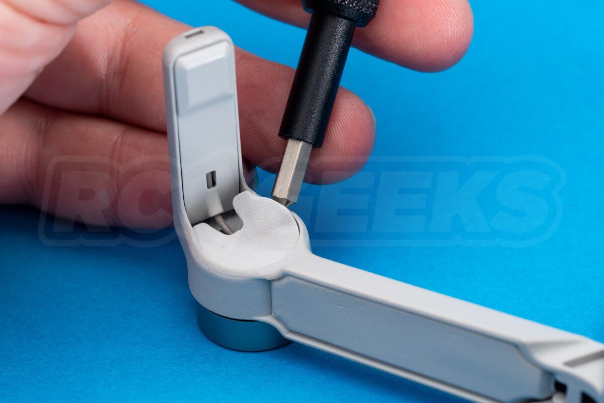
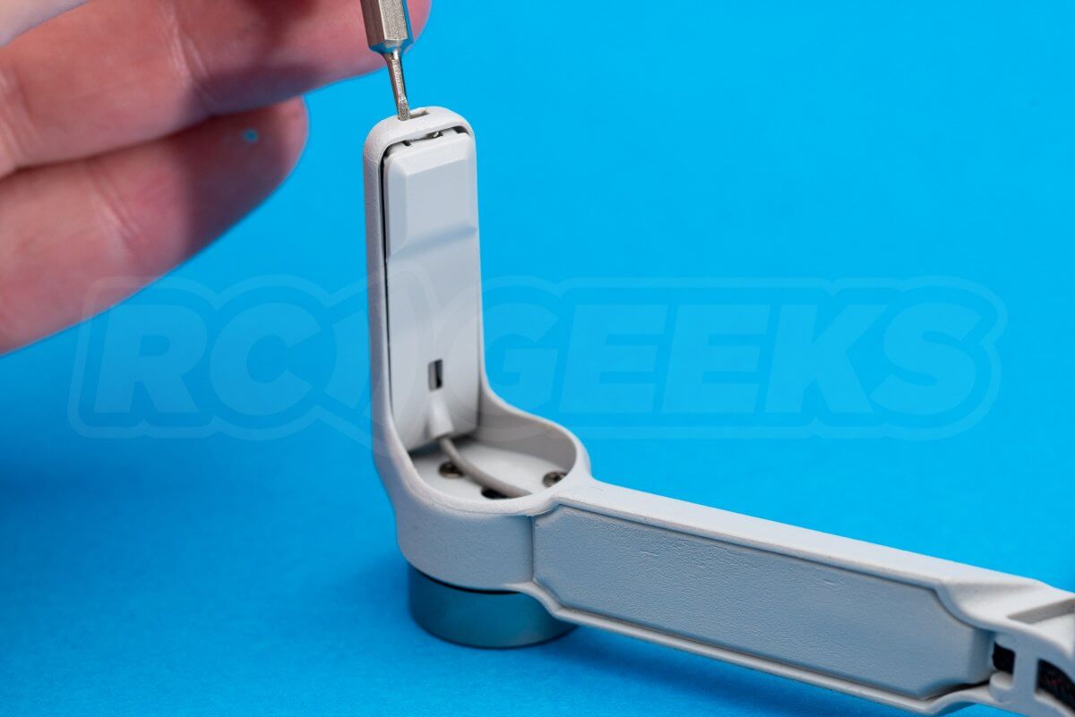
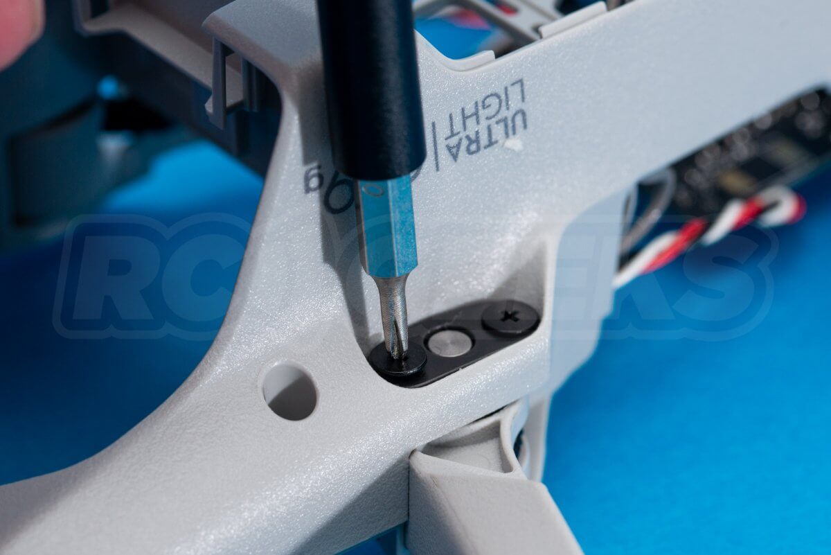
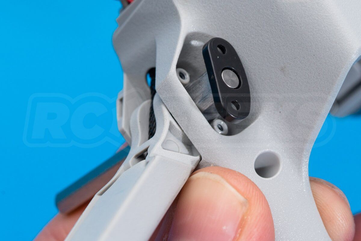
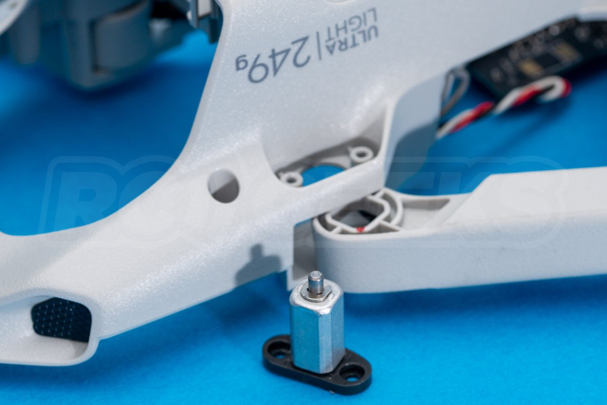
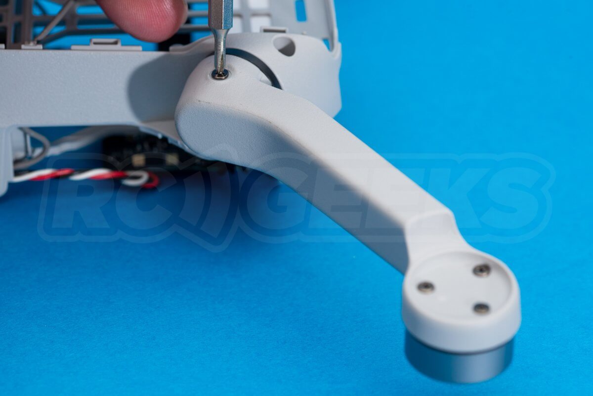
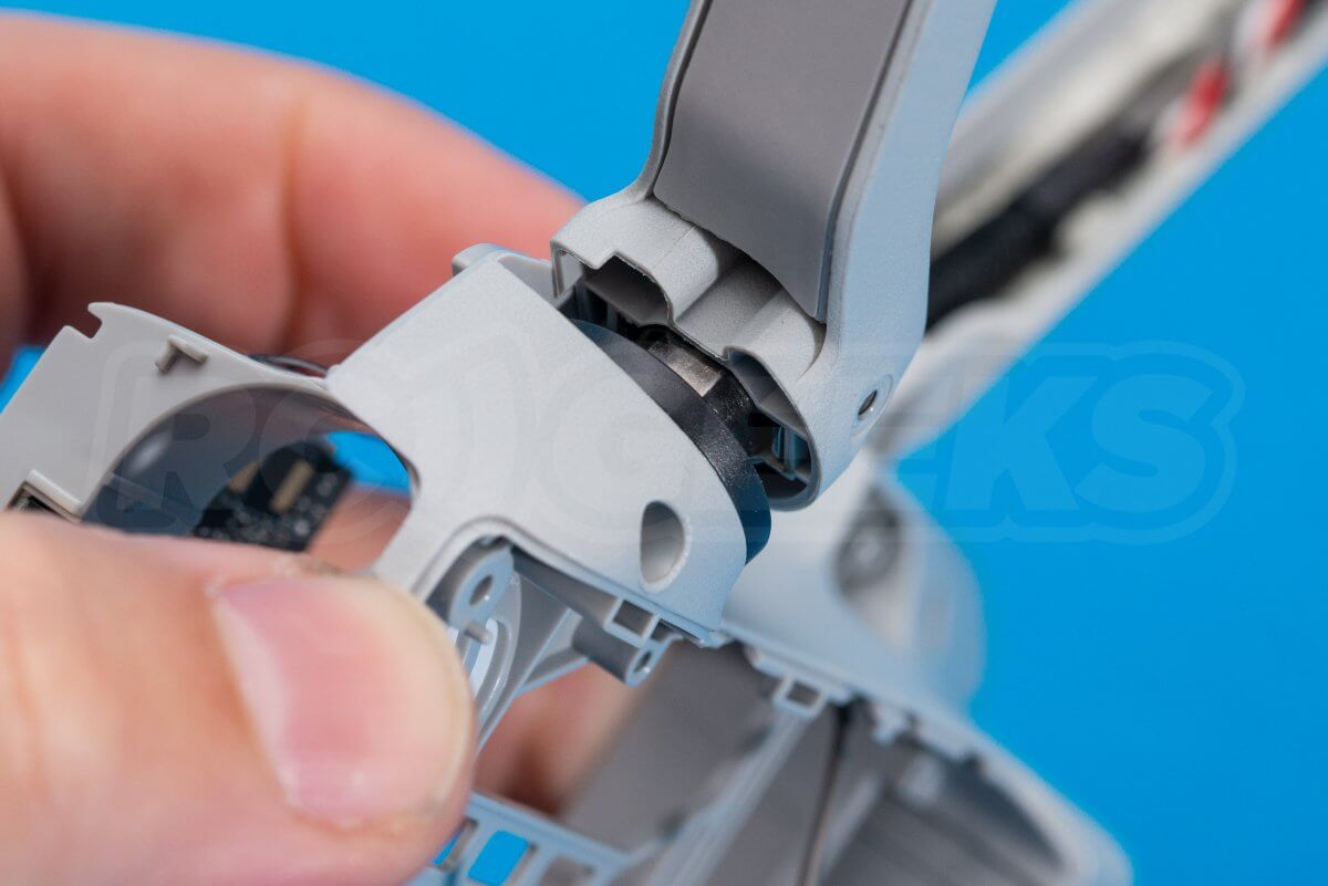
Should you need to remove the actual arm, the hinge must be released. Unscrew the two black cross head screws from the underside of the hinge, flip the drone over the push the shiny pin through from the other side. The hinge pin will drop out the other side. We repeated this process for the opposing leg.
For the rear legs, the process is a little different. The three motor screws are visible under the arms and can be easily removed with a cross head screwdriver.
With the legs rotating out instead of hinging, the legs retain to the frame via two cross head screws, one on top and one below. When removed the leg can be popped off of the top of the rotating hinge.
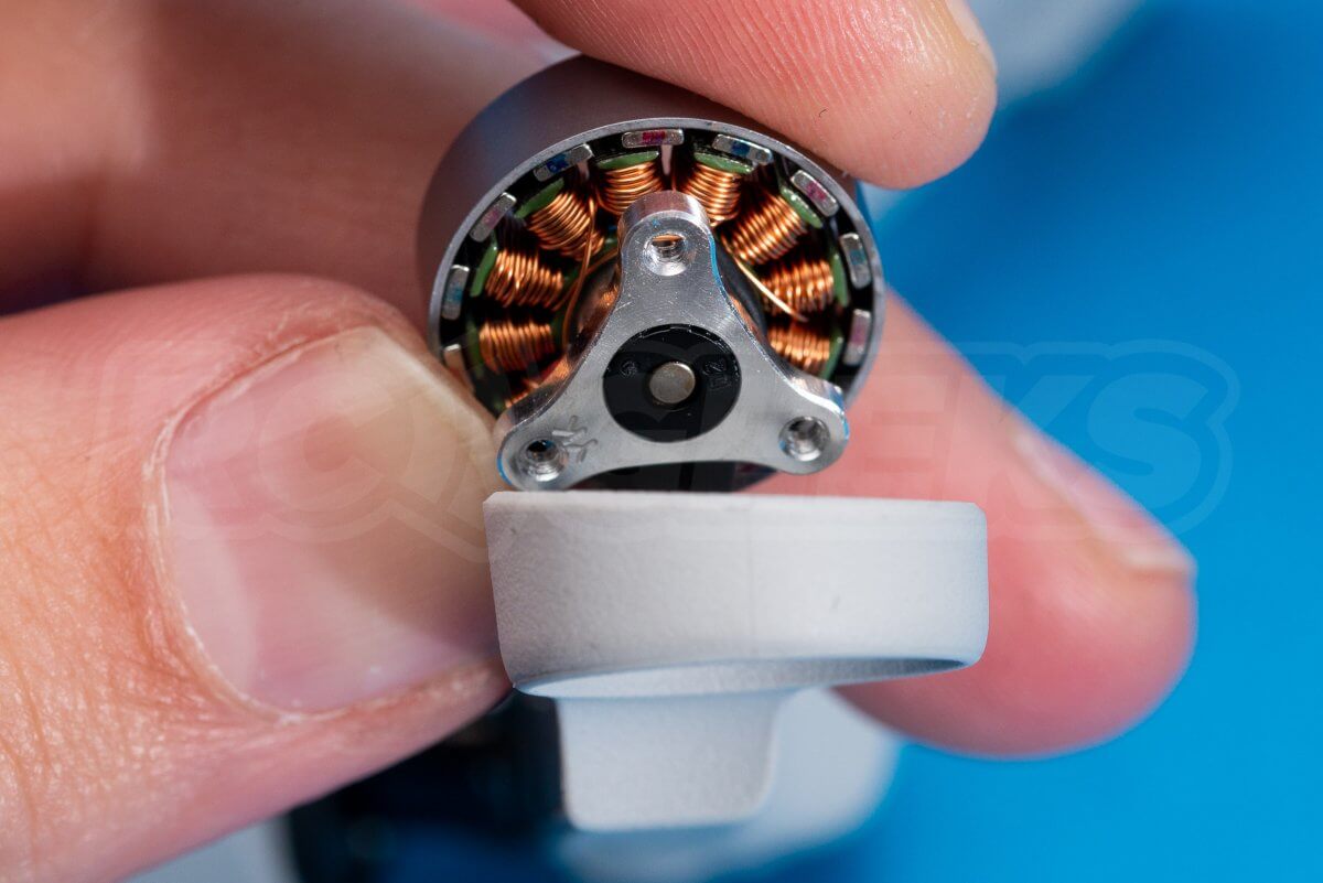
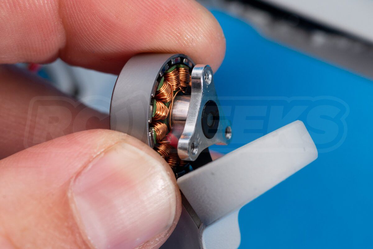
The tiny brushless motors have fourteen sets of windings and sit on metal mounts.
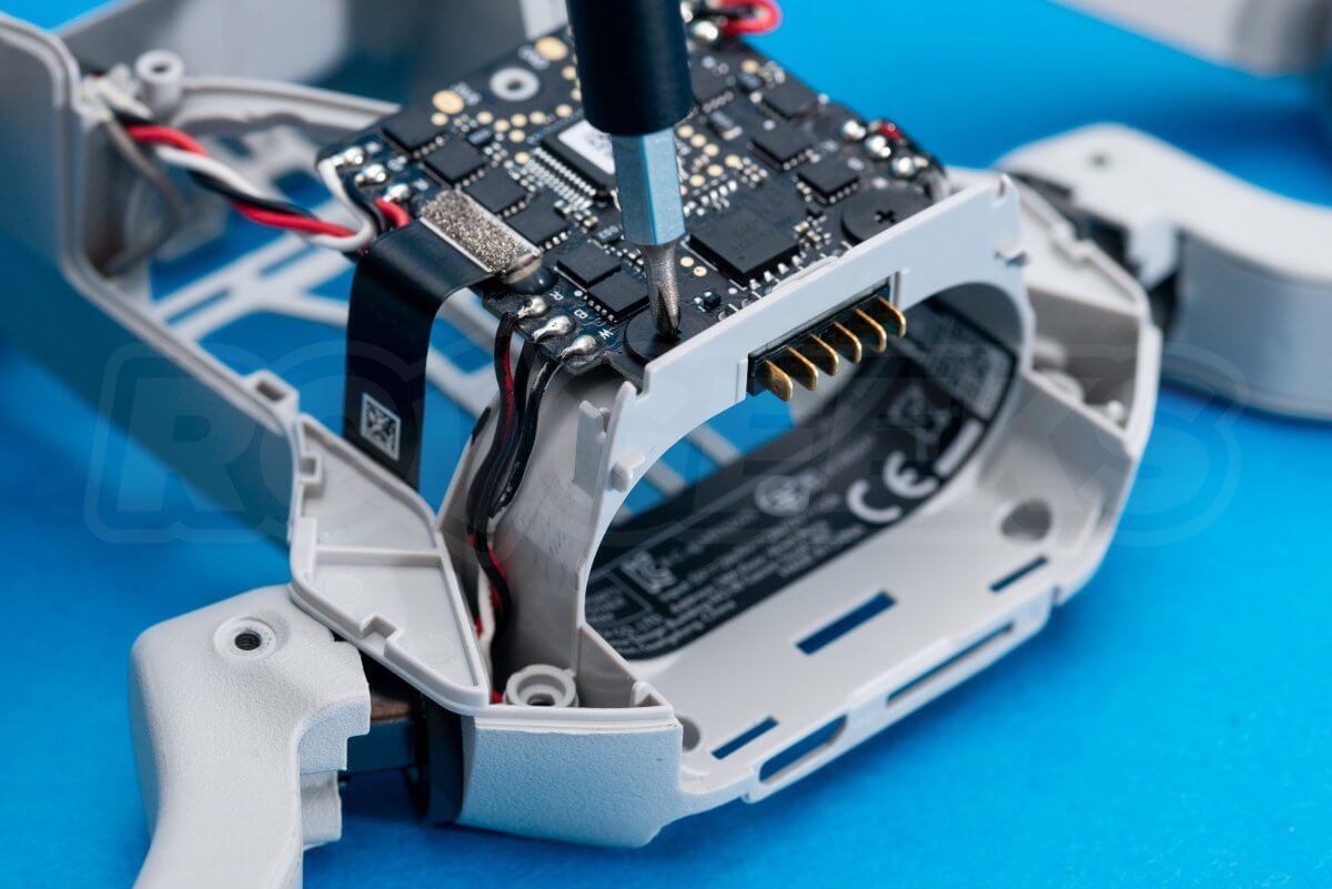
Lastly the power distribution and ESC board is retained by two shallow black screws and rubber washers.
Dismantling the battery
NOTE: We strongly recommend against doing this!
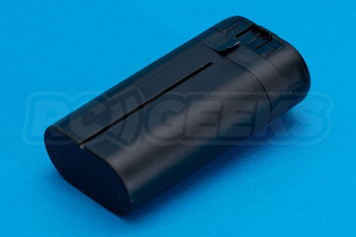
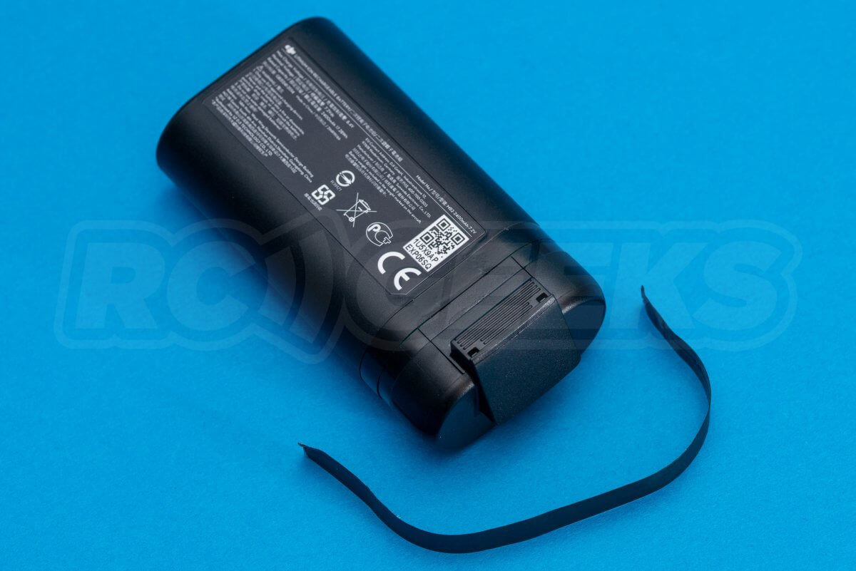
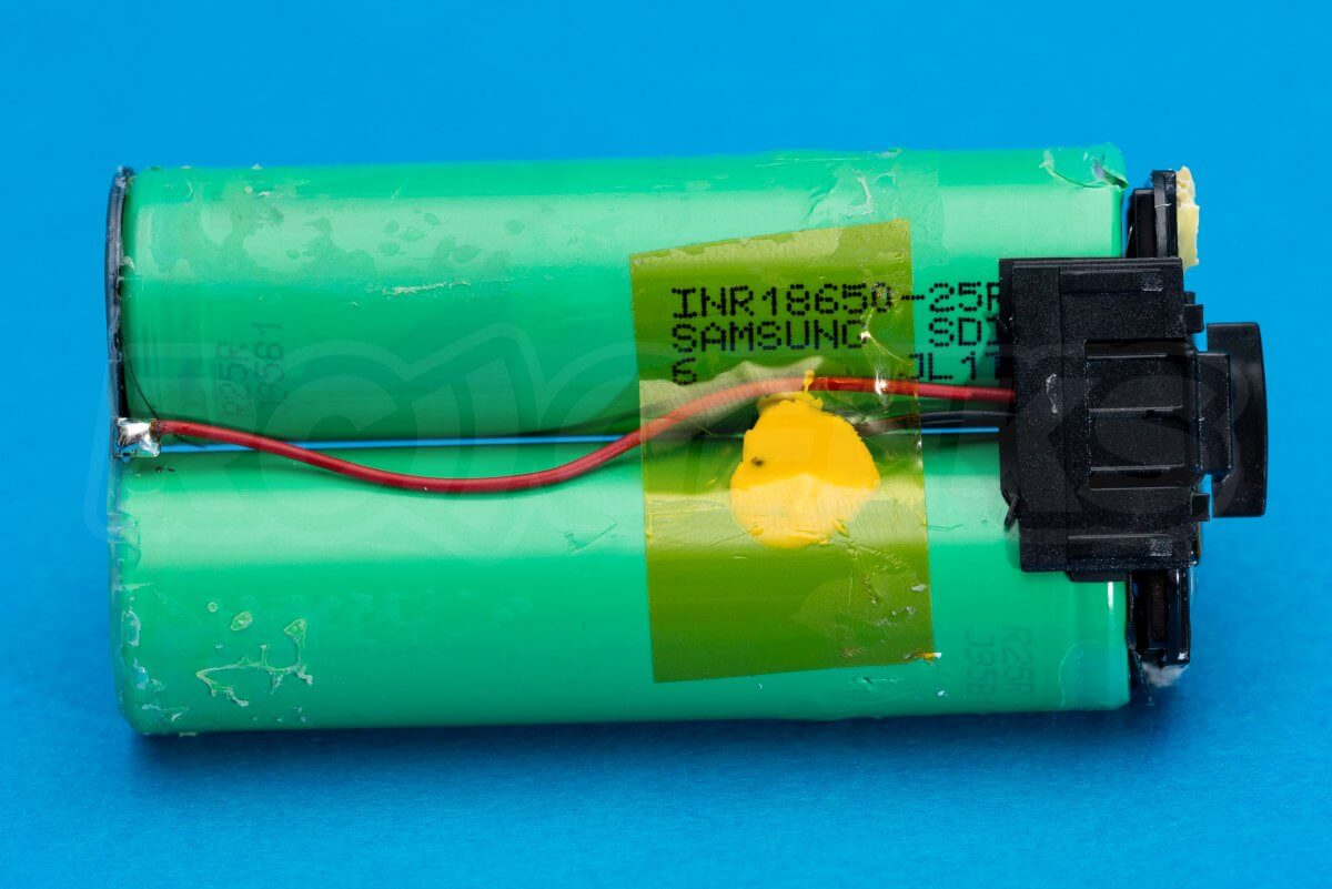
The battery consists of two Samsung 18650 cells soldered to a tiny battery management system. DJI doubtless took this direction to mass produce batteries much cheaper than the custom layered cells they produced for the Mavic Pro drones.
Transmitter teardown
We had several requests to see inside the transmitter in our Mavic Air teardown so we shall briefly investigate the Mavic Mini unit.
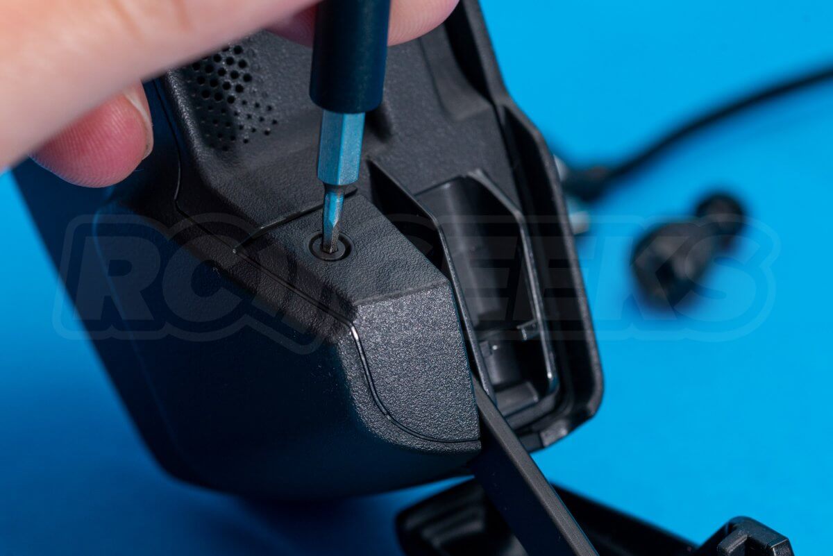
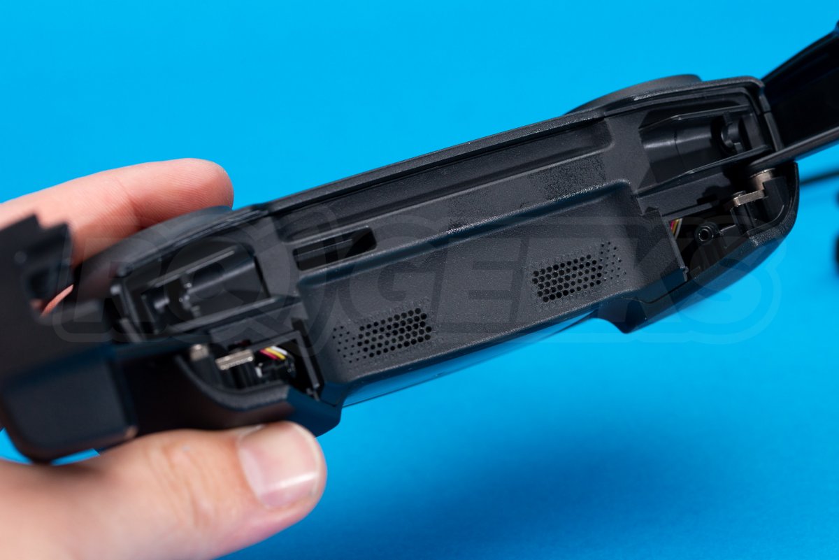
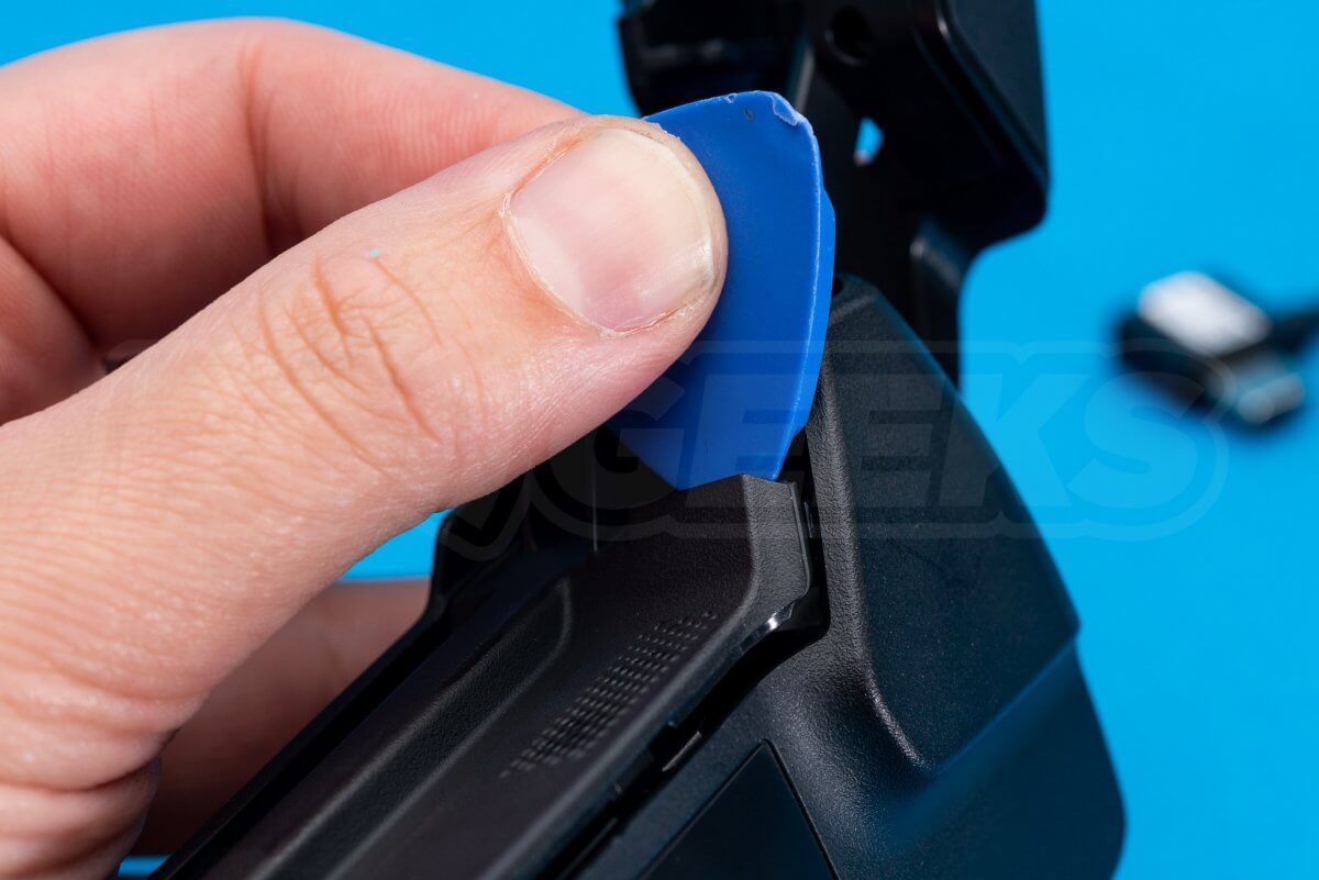
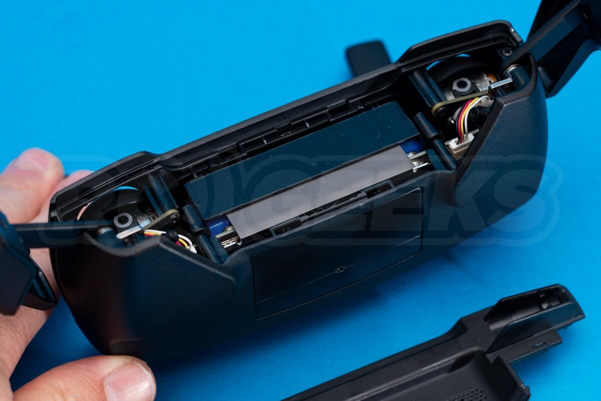
With the extension sticks removed, unscrew the two 1.5mm hex bolts at the bottom of the handset. Take a plastic tool and prise the lower plastic strip of the transmitter away.
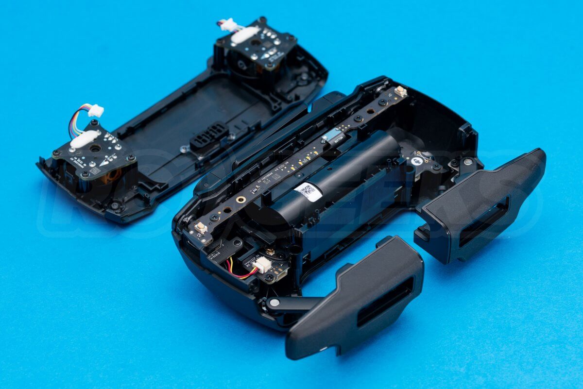
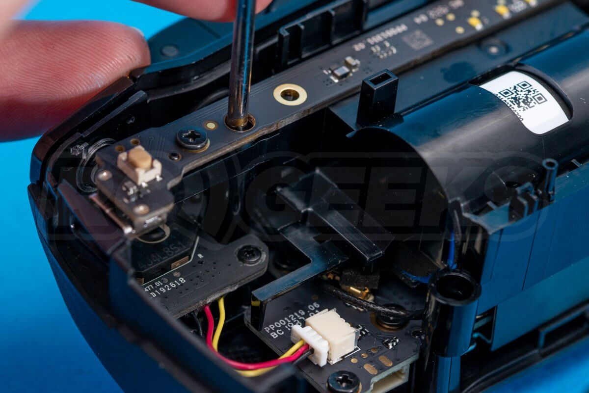
Next unscrew the two cross head screws in the top corners of the below photo. Carefully release the two communication cables for the stick pots using a flat-head screwdriver. The front of the transmitter can now be carefully popped off.
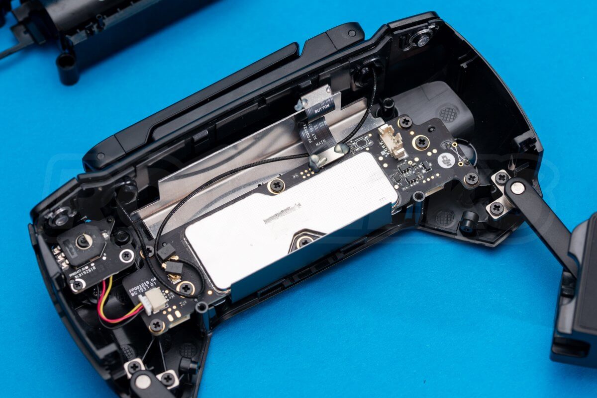
The shutter buttons and battery release from the back of the unit via four cross-head screws. Once removed the data cable and power plug need releasing before the entire set can be slid out of the way.
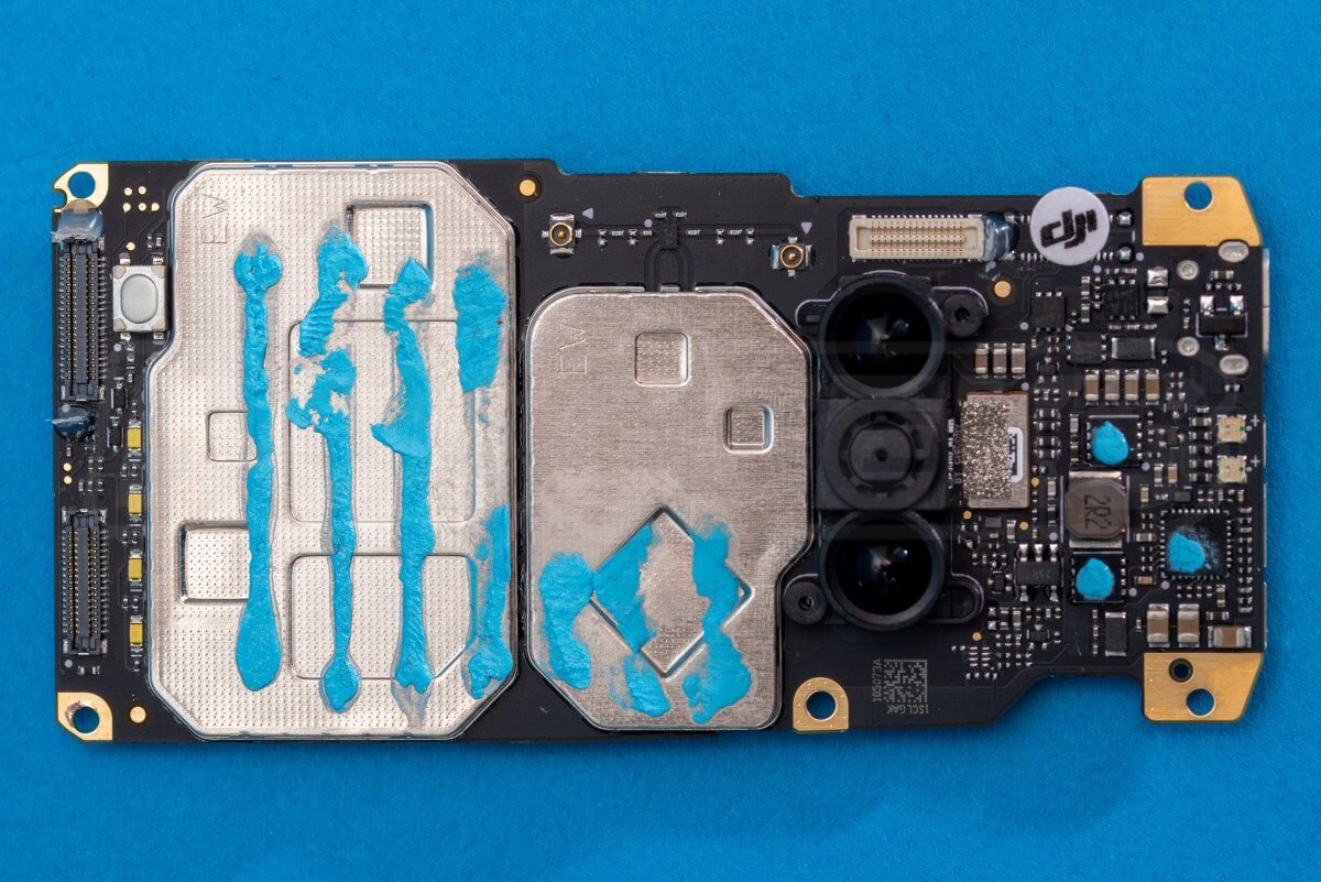
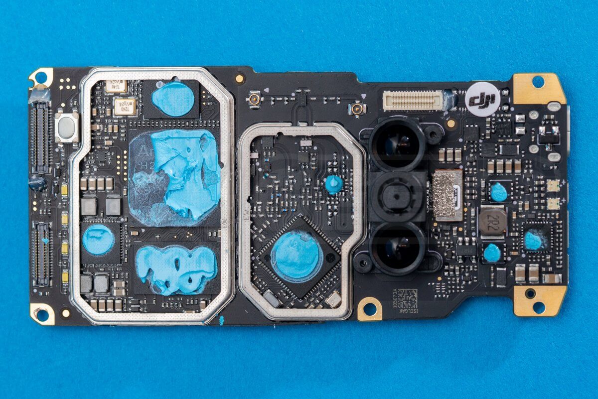
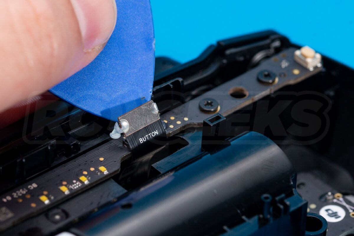
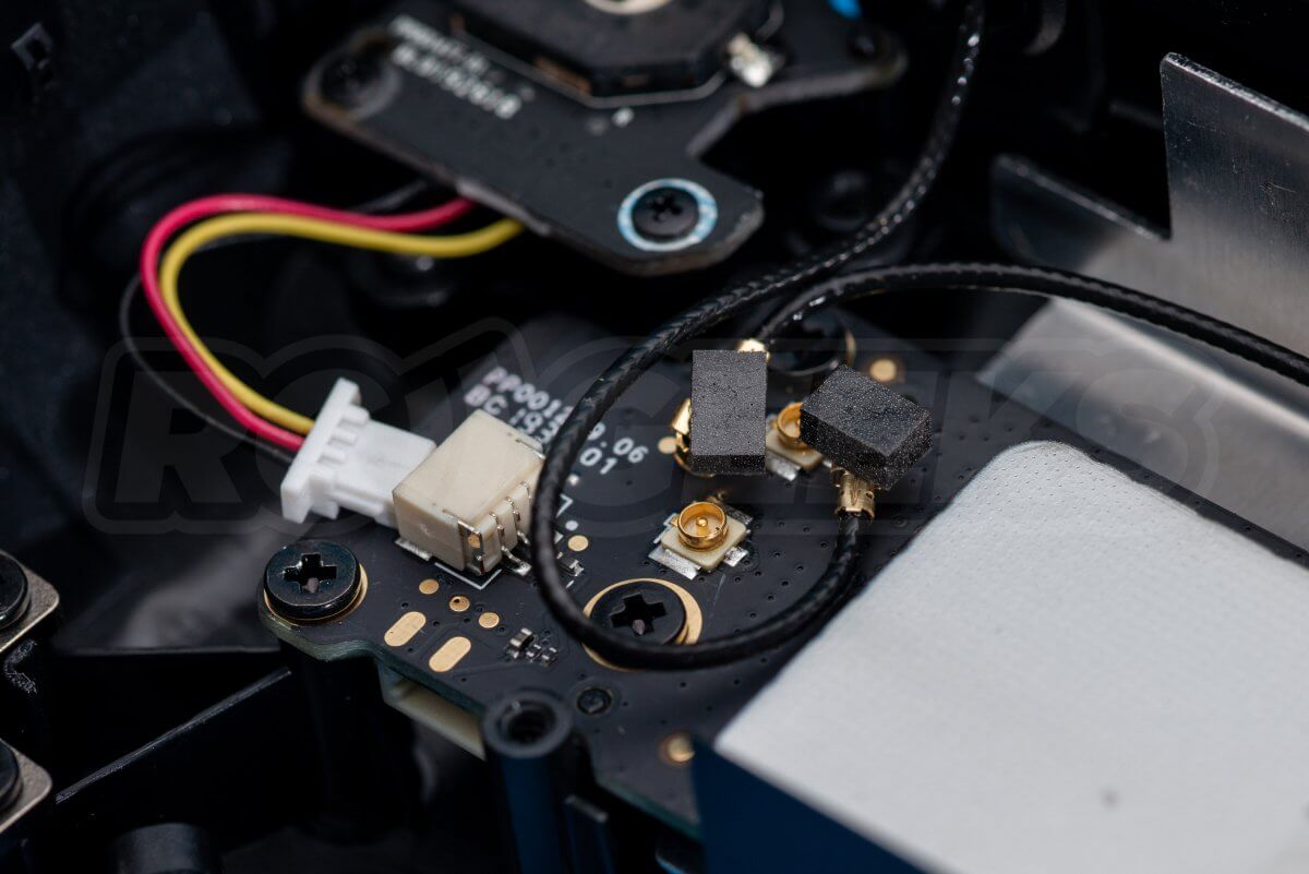
The transmitter processor board lives under the metal sheild shown below. Unplug the two antennas and remove the screws holding the panel down, taking note of the two different size of screw used.
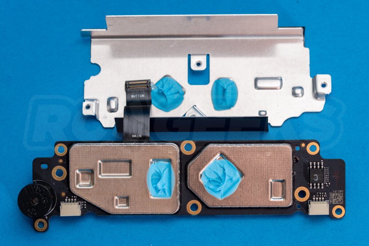
The processors sit under three heat spreaders, we have removed these and the thermal paste for a closer look.
Mavic Mini Teardown : In conclusion
That concludes our DJI Mavic Mini teardown. DJI should be commended for building a drone so compact, capable and yet so lightweight. At this price point (and more importantly, weight) the processor electronics were always going to be integrated into as few components as possible. Repairs, whilst possible, will likely be expensive.
You can order the drone from our webstore here. At time of posting we do not know what spares will be available from DJI for this drone but will update our store as we have more information. If you found this article interesting and would like to see others like it, check out the rest of our Teardown Series on our blog.
If you have any questions or would like anything clarified, feel free to drop us a message in the comments section below and we will do our best to get back to you.

