Our love of quadcopters runs deeper than just the Phantom consumer range of drones. To prove this we decided to put together our current top-of-the-range multirotor kit together; the Dji F550 Flame wheel.  We will be building the DJI Innovations F550 + Naza V2 + Gimbal + FPV + Ground Station Combo. It has combined all the best components to make a package that includes the DJI Groundstation for fully autonomous flight, with the Zenmuse gimbal for ultra-smooth video. It even includes the 5.8Ghz Datalink for FPV flight and the iOSD mini for showing real time flight data. With the Zenmuse gimbal costing £232 and the Naza V2 £191 alone, at a little over £800 this combo kit represents fantastic value.
  To start, we will need to construct the 6-arm frame, packaged neatly into this small box.
  Inside are 12 blades (two lengths, six of each), 6 x 30A opto ESC’s, 6 x 2212/920Kv motors, the power sharing baseplate, a top deck, 4 x red arms, 2 x white arms, fixing screws, Velcro straps and mounts, a power cable and a prop spanner.
  We opted to start at the ends of the arms and work our way in.
  This starts with screwing the motors onto the arms with four screws. The majority of the hex screws on the frame are 2.0mm.
  Then running the motor wires through the arm lattice to hang each of the ESC’s below the arms.
  It makes sense to solder the ESC’s to the board before fitting them to the frame, to get the cable length correct. Here we prepared the power cables with a webbed-sheath and heat shrink.
  The power distribution board comes marked out with positive and negative terminals. We will be soldering each of the ESC’s on as above.
  One by one the ESC’s were attached, face down to aid the wiring, leaving the control wire lose between the terminals.
  All six ESC’s are now attached to the baseplate which will distribute the power to them all.
  With the majority of the soldering complete, it was back to the construction. Here each of the legs has been attached to the base plate.
  Two of the larger hex screws at the lower end of each leg attach it to the baseplate, straddling the ESC wire.
  With the deans connectors back in stock, we created a battery lead in the same was as above and soldered that to the board. With the craft taking shape, it was time to start adding some of the control electronics.
  The kit comes with the excellent Naza V2 multirotor flight controller. Its own bright orange box contains the flight controller, the power management unit (PMU), LED indicator (which also houses the USB interface), GPS antenna/Compass with mount and connecting wires.
  For ease of later setup, we mounted the flight controller as centrally as possible, taking note of the direction of flight (the small arrow on top of the housing should point forward). Ignore the slightly messy baseplate as we were in the process of cleaning off the excess flux.
  For now, we attached the LED module to one of the rear legs of the craft, just to aid with the setup process. It was plugged into the LED port at the rear of the NAZA V2 flight controller. This module will be moved, potentially to the underside of the craft when complete to maximise visibility in the air.
  Whilst comprehensive, the kit does not include everything you need to fly. A transmitter and receiver are not included in the kit as we have found our customers have their own preferences when it comes to control systems. Having started out with Phantoms, we opted to install the DT7 radio kit. A simple and familiar controller, it has self-centering sticks, a gimbal angle lever and two additional switches for flight mode.
  he system includes the DR16 2.4Ghz receiver, a D-Bus type unit supporting 16 channels. With the DT7 handset we will be looking at a range of around a kilometre. It was installed using foam tape onto the baseplate and connected to the X2 port on the NAZA 2 unit.
  Next the power management unit (PMU) was soldered to the battery pickup terminals and installed on the opposite side to the flight controller to balance things out. This hooks up to the flight controller at the X3 port and has an expansion pass-through cable to the EXP port on the flight controller. At this point we also connected all the motor control wires to the leading edge of the NAZA in a clockwise fashion.
  With the basic flight electronics in place, we attached the top plate and tightened it down with the 24 hex bolts.
  The craft just needs a compass and antenna to fly. We mounted the stand at the front of the craft to one side and glued the shaft into the baseplate.
  The GPS antenna and compass is then stuck on top with the included 3M tape. Again it is important to point the antenna in the forward direction. It was plugged into the EXP port on the PMU to complete the wiring. At this point we measured the distance between the centre of the craft and the antenna for the later configuration of the NAZA V2 unit.
  With open frame craft it’s always a good idea to ensure everything is locked down. The ESC’s were secured with cable ties onto the arms. Motor and data cables were also tied down between the platforms.
  We added the included basic landing legs. Note the orientation when installing these to the F550 frame; they are set wider than on the F450.
  The 10inch props were fitted (writing side up) to the motors, taking care to mount them alternately around the craft before tightening the motor cap down with the supplied prop spanner.
  Another shot showing all the propellers installed, note that the craft is not ready to fly yet. We must connect it to the NAZA assist software to ensure the motors are wired correctly and to set up the antenna positions amongst other settings.
  A final shot from today. We test-fitted a Turnigy 3S 5000mAh to the top plate, using the supplied Velcro strap and some cable ties just for configuration. Having this much weight on-top of the frame is less than ideal for flight and it will be repositioned accordingly. The battery has a deans adaptor attached to mate it with the power board. Tune in for the next part next week where we configure the craft using the NAZA assist software and start adding some more advanced components!
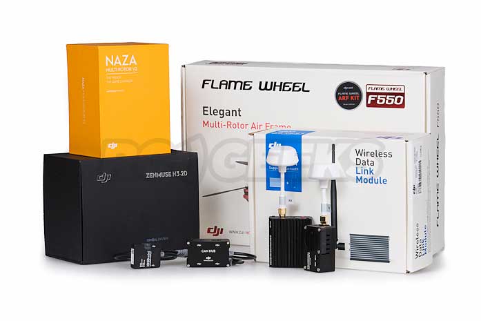 We will be building the DJI Innovations F550 + Naza V2 + Gimbal + FPV + Ground Station Combo. It has combined all the best components to make a package that includes the DJI Groundstation for fully autonomous flight, with the Zenmuse gimbal for ultra-smooth video. It even includes the 5.8Ghz Datalink for FPV flight and the iOSD mini for showing real time flight data. With the Zenmuse gimbal costing £232 and the Naza V2 £191 alone, at a little over £800 this combo kit represents fantastic value.
 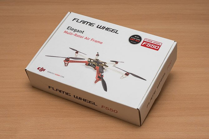 To start, we will need to construct the 6-arm frame, packaged neatly into this small box.
  Inside are 12 blades (two lengths, six of each), 6 x 30A opto ESC’s, 6 x 2212/920Kv motors, the power sharing baseplate, a top deck, 4 x red arms, 2 x white arms, fixing screws, Velcro straps and mounts, a power cable and a prop spanner.
  We opted to start at the ends of the arms and work our way in.
  This starts with screwing the motors onto the arms with four screws. The majority of the hex screws on the frame are 2.0mm.
  Then running the motor wires through the arm lattice to hang each of the ESC’s below the arms.
  It makes sense to solder the ESC’s to the board before fitting them to the frame, to get the cable length correct. Here we prepared the power cables with a webbed-sheath and heat shrink.
  The power distribution board comes marked out with positive and negative terminals. We will be soldering each of the ESC’s on as above.
  One by one the ESC’s were attached, face down to aid the wiring, leaving the control wire lose between the terminals.
  All six ESC’s are now attached to the baseplate which will distribute the power to them all.
  With the majority of the soldering complete, it was back to the construction. Here each of the legs has been attached to the base plate.
  Two of the larger hex screws at the lower end of each leg attach it to the baseplate, straddling the ESC wire.
  With the deans connectors back in stock, we created a battery lead in the same was as above and soldered that to the board. With the craft taking shape, it was time to start adding some of the control electronics.
  The kit comes with the excellent Naza V2 multirotor flight controller. Its own bright orange box contains the flight controller, the power management unit (PMU), LED indicator (which also houses the USB interface), GPS antenna/Compass with mount and connecting wires.
  For ease of later setup, we mounted the flight controller as centrally as possible, taking note of the direction of flight (the small arrow on top of the housing should point forward). Ignore the slightly messy baseplate as we were in the process of cleaning off the excess flux.
  For now, we attached the LED module to one of the rear legs of the craft, just to aid with the setup process. It was plugged into the LED port at the rear of the NAZA V2 flight controller. This module will be moved, potentially to the underside of the craft when complete to maximise visibility in the air.
  Whilst comprehensive, the kit does not include everything you need to fly. A transmitter and receiver are not included in the kit as we have found our customers have their own preferences when it comes to control systems. Having started out with Phantoms, we opted to install the DT7 radio kit. A simple and familiar controller, it has self-centering sticks, a gimbal angle lever and two additional switches for flight mode.
  he system includes the DR16 2.4Ghz receiver, a D-Bus type unit supporting 16 channels. With the DT7 handset we will be looking at a range of around a kilometre. It was installed using foam tape onto the baseplate and connected to the X2 port on the NAZA 2 unit.
 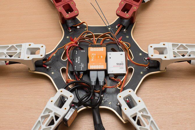 Next the power management unit (PMU) was soldered to the battery pickup terminals and installed on the opposite side to the flight controller to balance things out. This hooks up to the flight controller at the X3 port and has an expansion pass-through cable to the EXP port on the flight controller. At this point we also connected all the motor control wires to the leading edge of the NAZA in a clockwise fashion.
  With the basic flight electronics in place, we attached the top plate and tightened it down with the 24 hex bolts.
  The craft just needs a compass and antenna to fly. We mounted the stand at the front of the craft to one side and glued the shaft into the baseplate.
  The GPS antenna and compass is then stuck on top with the included 3M tape. Again it is important to point the antenna in the forward direction. It was plugged into the EXP port on the PMU to complete the wiring. At this point we measured the distance between the centre of the craft and the antenna for the later configuration of the NAZA V2 unit.
  With open frame craft it’s always a good idea to ensure everything is locked down. The ESC’s were secured with cable ties onto the arms. Motor and data cables were also tied down between the platforms.
  We added the included basic landing legs. Note the orientation when installing these to the F550 frame; they are set wider than on the F450.
  The 10inch props were fitted (writing side up) to the motors, taking care to mount them alternately around the craft before tightening the motor cap down with the supplied prop spanner.
 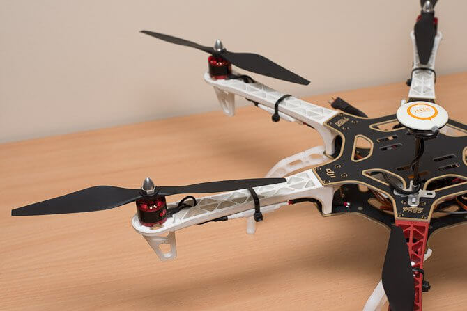 Another shot showing all the propellers installed, note that the craft is not ready to fly yet. We must connect it to the NAZA assist software to ensure the motors are wired correctly and to set up the antenna positions amongst other settings.
  A final shot from today. We test-fitted a Turnigy 3S 5000mAh to the top plate, using the supplied Velcro strap and some cable ties just for configuration. Having this much weight on-top of the frame is less than ideal for flight and it will be repositioned accordingly. The battery has a deans adaptor attached to mate it with the power board. Tune in for the next part next week where we configure the craft using the NAZA assist software and start adding some more advanced components!
-

-

-

-

-

-

-

-

-

-
-
-

-

-

-

-

-

-

-

-

-

-

-
 reviews
Axial SCX10 II Jeep Cherokee Scale Crawler Review : Does it live up to its reputa...
Tom Begley | -

-

-

-

-

-

-

-

-

-

-

-

-

-

-
-
-

-

-

-

-

-

-
 tutorial
Mavic 2 & DJI Goggles : The ultimate pairing in filming, inspections & surveys
Tom Begley | -

-

-

-

-

-

-

-

-

-

-

-

-

-

-

-

-

-

-
 reviews
FrSKY's Taranis Q X7 Transmitter - A budget alternative to the Taranis Plus X9D?
Tom Begley | -

-

-

-

-

-

-

-

-

-

-

-

-

-

-

-

-

-

-

-

-

-

-

-

-

-

-

-

-

-

-

-

-

-

-

-

-

-

-

-

-

-


