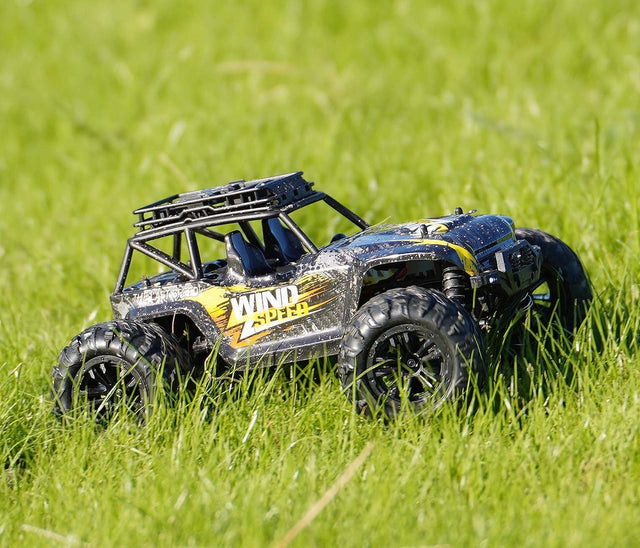
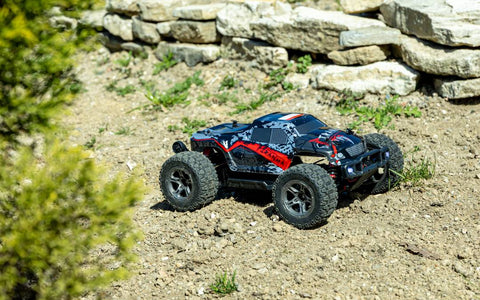
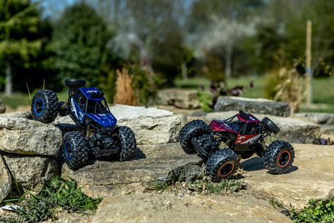
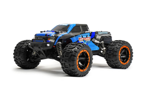
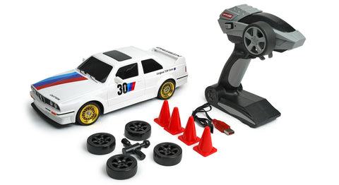
Below you will find a step by step guide on how to replace the following on your RCG Racing Wind Speed or Storm Rider: Any spare parts needed you can order from our website.
You can see a parts diagram by clicking here.
1 - Replacing The Motor
2 - Replacing The 2-in-1 Unit
3 - Replacing The Rear Diff
4 - Replacing The Front Diff
5 - Replacing The Servo
6 - Replacing Front Driveshafts
Please note. These steps are to be taken as a guide only. RC Geeks can not accept responsibility for damage done to the vehicle or parts.
For all repairs you will need to remove the bodyshell. You can do this by removing the below 4 clips:

We also recommend disconnecting and removing the battery before doing any repairs. Please disconnect the wire and remove the battery cover with the below clip:

Replacing the Motor
1 - After removal of the bodyshell and battery, now the upper chassis plate will need to be removed. The part number for this is G16-10.
In total 8 screws will need to be removed, 6 from the top and 2 at the rear.


2 - Following this, the rear upper suspension arms (G16-09) will need to be disconnected from the upper chassis plate.

3 - Please now remove the rear shock absorbers (G16-29) from the rear shock mount. The upper chassis plate should now be free from the model.

4 - The motor can now be disconnected from the two in one unit by simply pulling the connector out of the board. The motor should now be free from the car.
5 - Finally the motor mount can be removed and now the motor can be replaced for a new one.

Replacing the 2-in-1 Unit
1 - After removal of the bodyshell and battery, now the upper chassis plate will need to be removed. The part number for this is G16-10.
In total 8 screws will need to be removed, 6 from the top and 2 at the rear.


2 - Following this, the rear upper suspension arms (G16-09) will need to be disconnected from the upper chassis plate.

3 - Please now remove the rear shock absorbers (G16-29) from the rear shock mount. The upper chassis plate should now be free from the model.

4 - There should be three screws holding the cover to the two in one unit to the model. These can be removed.

5 - Finally, please disconnect the motor and servo by pulling the connectors out of the two in one unit. This unit can now be replaced and the car reassembled.
Replacing The Rear Diff
1 - After removal of the bodyshell and battery, now the upper chassis plate will need to be removed. The part number for this is G16-10.
In total 8 screws will need to be removed, 6 from the top and 2 at the rear.


2 - Following this, the rear upper suspension arms (G16-09) will need to be disconnected from the upper chassis plate.

3 - Please now remove the rear shock absorbers (G16-29) from the rear shock mount. The upper chassis plate should now be free from the model.

4 - The rear differential should be clearly visible and can be removed by hand. Please replace this differential and reassemble the model.

Replacing The Front Diff
1 - After removal of the bodyshell and battery, now the upper chassis plate will need to be removed. The part number for this is G16-10.
In total 8 screws will need to be removed, 6 from the top and 2 at the rear.


2 - Following this, the rear upper suspension arms (G16-09) will need to be disconnected from the upper chassis plate.

3 - Please now remove the rear shock absorbers (G16-29) from the rear shock mount. The upper chassis plate should now be free from the model. In addition to this, it would be worth unscrewing the front shock absorbers as this will be relevant later.

4 - The front bumper will now need removing. This can be accomplished by unscrewing the three Phillips head screws on the underside chassis of the device.

5 - Now we will be removing the front gearbox cover (G16-12). There will be 2 remaining screws to remove, please see below:

6 - Now the front differential should be visible and can be removed by hand.

Replacing the Servo
1 - After removal of the bodyshell and battery, now the upper chassis plate will need to be removed. The part number for this is G16-10.
In total 8 screws will need to be removed, 6 from the top and 2 at the rear.


2 - Following this, the rear upper suspension arms (G16-09) will need to be disconnected from the upper chassis plate.

3 - Please now remove the rear shock absorbers (G16-29) from the rear shock mount. The upper chassis plate should now be free from the model.

5. Remove the 3 screws from the ESC (right), enabling you to disconnect the servo wire.

6 - Remove the 3 screws holding in the servo.

7. Disconnect the Servo arm by removing the below screw.

8. Now simply disconnect the servo and replace with the new one.
Replacing the Front Driveshafts
1. After removal of the bodyshell and battery, you will need to remove the front bumper

2. Now that you have access to the suspension arms, you will need to remove the exposed pins located at the bottom. To make it easier you can also remove the shock absorber on the affected side.

4. You will now have enough clearance to remove the drive shaft which should come out at an angle on one side.
5. Simply put in the new driveshaft and put the screws and pins back together.

